Enthalpy extractor for hydrocarbon vapors

a technology of hydrocarbon vapor and extractor, which is applied in the direction of liquid transfer devices, transportation and packaging, packaging goods types, etc., can solve the problems of escaping such vapors somewhere in the system into the atmosphere, and achieve the effect of reducing the pressure of vapors

Inactive Publication Date: 2006-02-21
HUSKY CORP
View PDF11 Cites 9 Cited by
  • Summary
  • Abstract
  • Description
  • Claims
  • Application Information

AI Technical Summary

Benefits of technology

[0007]The principal object of this invention is to provide means for chilling the vapor's returning to the underground storage tank, at various locations, for the purpose of contracting the vapors, providing some condensing of them, and as a result, providing a measured reduction in the pressure of the vapors that allows for more of such vapors to be stored, and at a lesser pressure.
[0010]Observations have been made, and tests conducted, of Phase II vapor recovery systems, of the vapor pressure in the fuel storage tanks that are caused by such systems, and because of the excessive pressure of such stored vapors, can cause this escape of such vapors somewhere in the system into the atmosphere. It is now recognized by the inventors herein that by cooling such vapors, their pressure can be reduced to near zero, and thereby lessening the chance that any vapors may escape into the atmosphere.
[0014]The removal of one BTU of heat will cool 333 gallons of vapor 1° Fahrenheit. To cool 10,000 gallons of vapor, at least 1°, would require the removal of approximately 30 BTUs. 30 BTUs per minute of heat removal is 1,800 BTUs per hour, equal to 0.15 tons of refrigeration. This very small type of refrigeration unit, as referred to herein, can easily keep the pressure from increasing as actual testing has shown, such that when a station is shut down, the pressure will not increase at more than the average of 1 inch of water column per hour, and would therefore only require a temperature reduction of 1° per hour, which is a miniscule amount, for any type of small unit, and even a small or standard form of refrigeration equipment can be employed. Locating the equipment in the manner as previously summarized can easily attain that type of temperature reduction, in order to have the effects as desired from this invention.
[0018]The advantages of this current system, over what has been done previously in the past, include lower initial costs, ease of instillation, lowering the operating costs, and simple maintenance, which can be serviced by any available trained maintenance personnel. Any maintenance personnel, having the slightest information relative to standard refrigeration equipment, and its maintenance, can take care of the servicing of the vapor cooler of this invention.
[0019]It is, therefore, the principal object of this invention to provide a refrigeration system for reducing the temperature of any vapors returned to underground storage during fuel dispensing, in order to lessen the pressure of those vapors in the tank, to prevent their escape, or to cause any leakage in the underground storage tank, due to a build up of excessive pressures.

Problems solved by technology

Observations have been made, and tests conducted, of Phase II vapor recovery systems, of the vapor pressure in the fuel storage tanks that are caused by such systems, and because of the excessive pressure of such stored vapors, can cause this escape of such vapors somewhere in the system into the atmosphere.

Method used


Image

  • Enthalpy extractor for hydrocarbon vapors
  • Enthalpy extractor for hydrocarbon vapors

Examples


Embodiment Construction

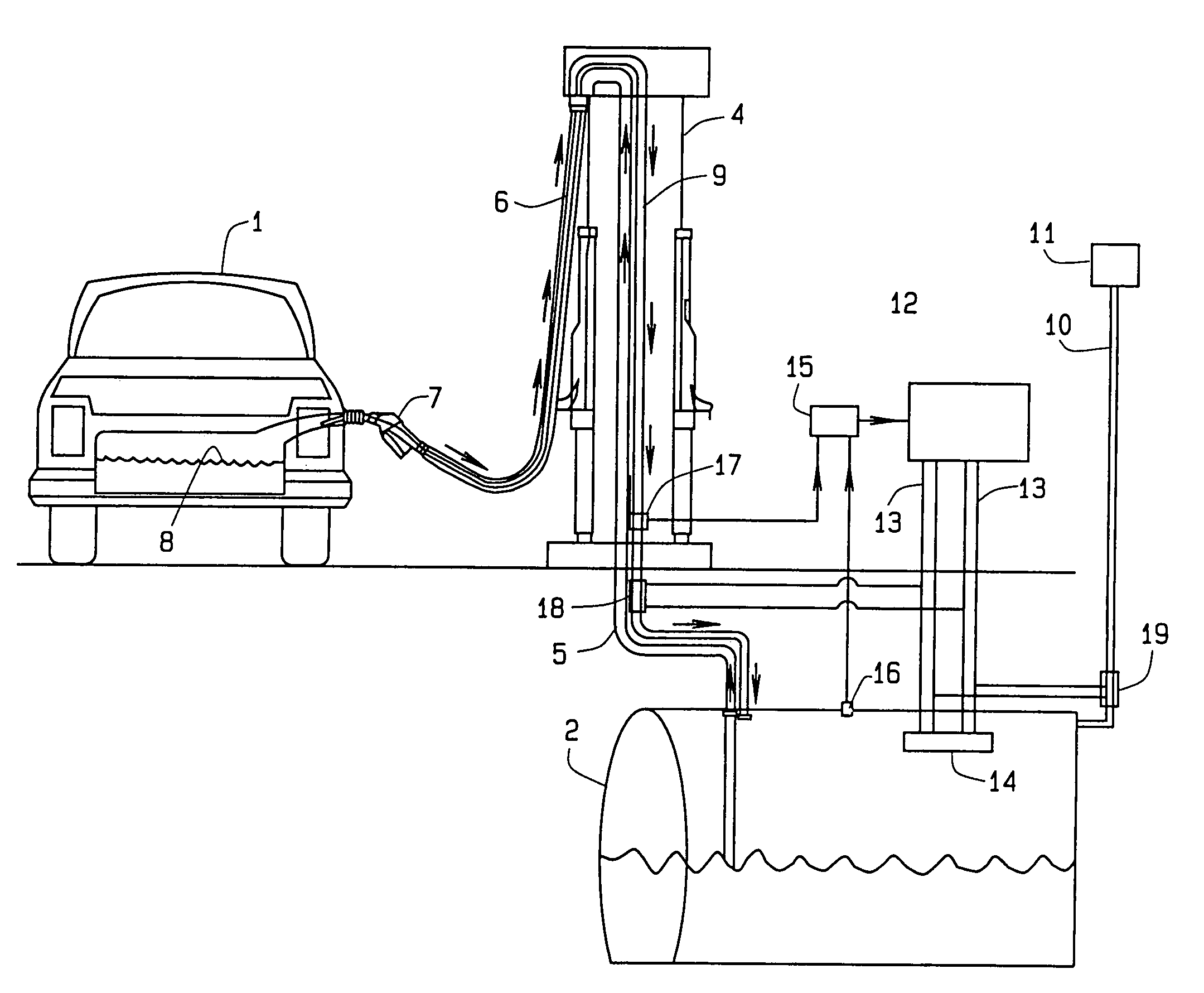
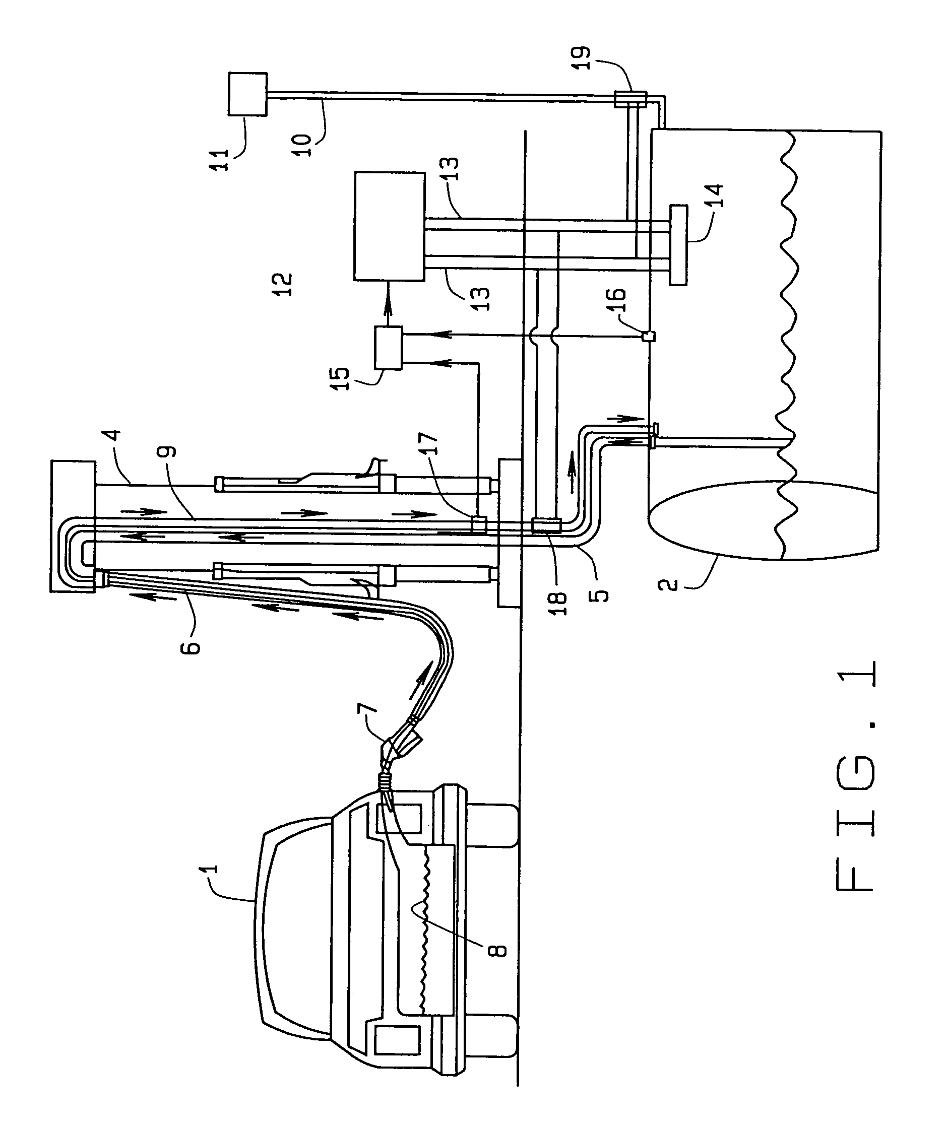
[0022]In referring to the drawing, and in particular FIG. 1, the standard method for dispensing of fuel to an automobile, as at 1, is through usage of an underground storage tank 2 at the service station, which contains a quantity of stored fuel 3, and a dispenser 4, which when initiated, pumps the fuel by way of the fuel line 5, through a coaxial hose 6, through the nozzle 7 and into the vehicle fuel tank 8, as can be noted. As is well known in the art, these coaxial hoses provide for the flow of fuel through one segment of the concentric hose, while the other portion of the hose returns vapors back into the underground storage tank, through the vapor line 9, as can be seen. In addition, a vent line 10 normally communicates with the upper vapor section of the underground storage tank, and disposes a vent 11, up in the air, in order to vent any vapors that may attain excessive pressure, to the atmosphere.

[0023]The subject matter of this current invention is the application of a refr...


PUM

PropertyMeasurementUnit
vapor pressureaaaaaaaaaa
pressureaaaaaaaaaa
temperatureaaaaaaaaaa

Abstract

A fuel storage tank vapor cooler to effect pressure reduction, in a fuel dispensing system, including the application of a refrigeration unit, that operates under the effects of a control unit, sensitive to vapor pressures, and vapor flow, to initiate the operations of the refrigeration unit, and effecting, through a properly located heat exchanger, a reduction in the temperature of the stored vapors, and thereby reducing its incident pressure. Such heat exchangers may be located either within the vapor storage area of the underground storage tank, the heat exchanger may locate in cooperation with the vapor return line, to the underground storage tank, or it may be located within the vent line from the storage tank, to chill the vapors and thereby provide for a reduction in their pressure. Such heat exchangers may be used in combination, or individually, whatever is determined to obtain the results as desired from the system of this invention.

Description

CROSS REFERENCE TO RELATED APPLICATION[0001]This non-provisional patent application claims priority to the provisional patent application having Ser. No. 60 / 396,589, which was filed on Jul. 17, 2002.BACKGROUND OF THE INVENTION[0002]As well known in the art, particularly in the field of fuel dispensing, EPA, in addition to various state regulatory agencies, such as the California Air Resources Board, have placed stringent demands upon the oil companies, in addition to the supplier of equipment for use in dispensing fuel, to totally eliminate the escape of any vapors or fumes into the atmosphere. This pressure has been placed upon the oil companies, and which is imposed upon the supplier of equipment, such as the companies furnishing dispensers, the companies providing underground storage tanks, and even those companies that furnish fuel dispensing nozzles. All of the efforts are directed towards capturing the vapors, and returning them back to the underground storage tank. Of more re...

Claims


Application Information

Patent Timeline
Patent Type & Authority Patents(United States)
IPC IPC(8): B65B1/04B67D7/04
CPCB67D7/0476
Inventor FINK, JR., ARTHUR C.SUTCLIFFE, GRENVILLE G.
Owner HUSKY CORP
Why Eureka
Try Eureka