Output power split hybrid electric drive system

a hybrid electric drive and output power technology, applied in the direction of electric propulsion mounting, battery/cell propulsion, gearing, etc., can solve the problems of reducing fuel efficiency, increasing exhaust emissions, and limiting the effective driving torque of two wheels, and achieve high fuel efficiency

Inactive Publication Date: 2006-02-21
THE TIMKEN CO
View PDF19 Cites 83 Cited by
  • Summary
  • Abstract
  • Description
  • Claims
  • Application Information

AI Technical Summary

Benefits of technology

[0014]An objective of this invention is to provide a simple power split hybrid wheel drive system capable of providing individual infinitely variable speed and torque, as well as drive...

Problems solved by technology

The wide variation in driving engine speed reduces fuel efficiency and increases exhaust emissions.
When road surface variations at each wheel produce different coefficients of friction, the lower wheel driving torque of the two wheels limits the effective driving torque, which is twice the lowest wheel torque.
The application of torque in excess of the lowest wheel torque level results in spinning of the vehicle wheel.
Both IVT and CVT systems are capable of providing continuous speed ratio change between the driving engine and driven wheels, however, the output speed of an IVT can be reduced to zero and even reversed, while the output speed of a CVT cannot.
First, hydraulic drives are not suitable for high-speed operation.
This, to a large degree, limits hydro-mechanical IVT systems to non-automotive applications.
Secondly, hydrostatic pump or motors utilized in hydro-mechanical ...

Method used


Image

  • Output power split hybrid electric drive system
  • Output power split hybrid electric drive system
  • Output power split hybrid electric drive system

Examples


Embodiment Construction

[0043]The following detailed description illustrates the invention by way of example and not by way of limitation. The description clearly enables one skilled in the art to make and use the invention, describes several embodiments, adaptations, variations, alternatives, and uses of the invention, including what is presently believed to be the best mode of carrying out the invention.

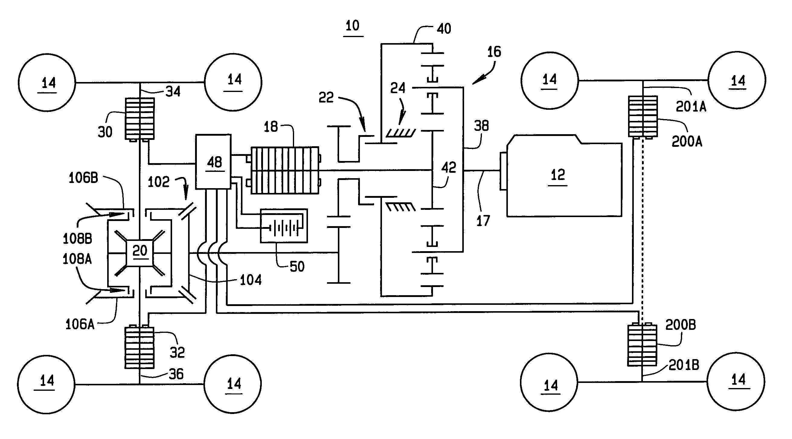
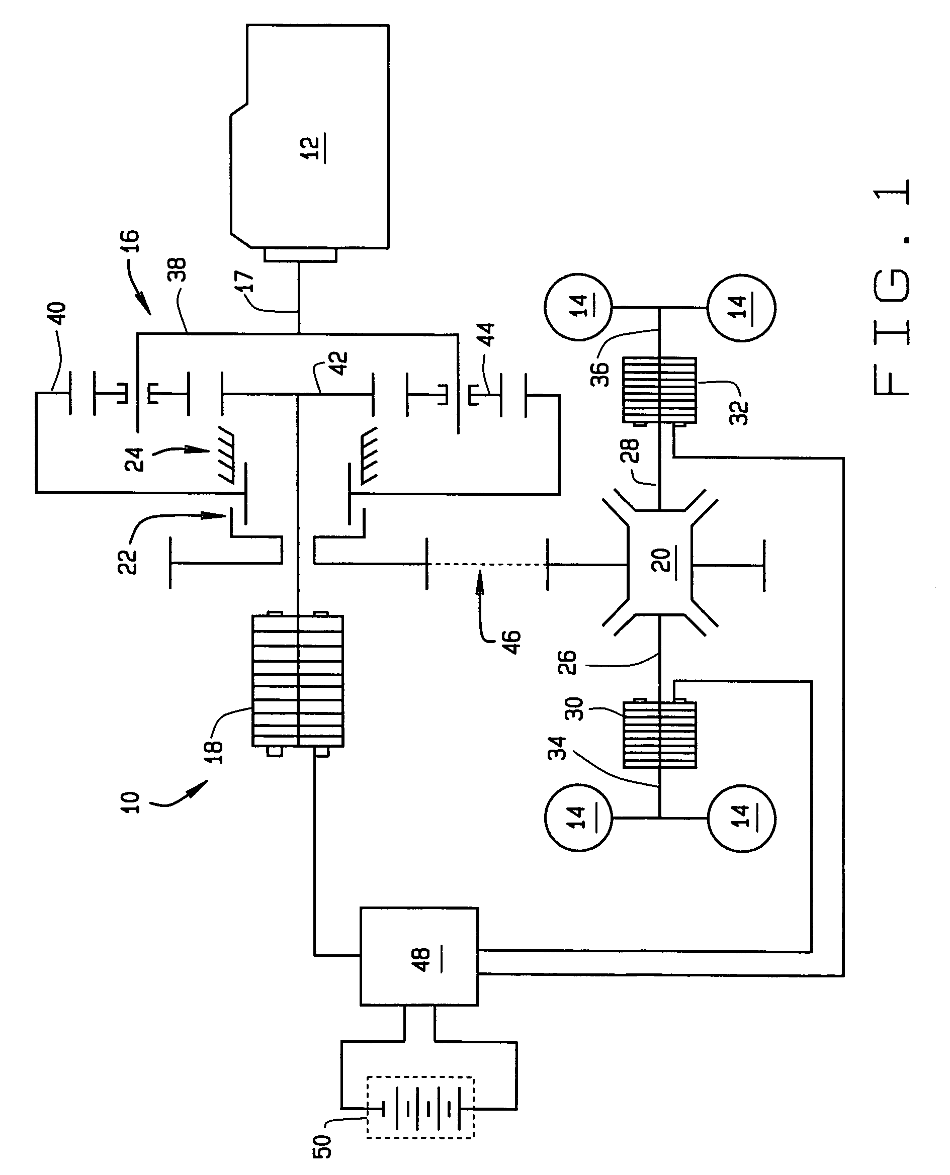
[0044]Referring to FIG. 1, there is shown a first embodiment of the drive system 10 of the present invention, coupled between a driving engine 12 and a set of driven wheels 14. The drive system 10 comprises planetary gear train, indicated generally at 16, driven by an output shaft 17 from the driving engine 12. Output from the planetary gear train 16 is split between a primary electric motor (generator) 18 and a mechanical differential gearbox 20. Output from the planetary gear train 16 is regulated by a mechanical clutch 22 and a brake system 24.

[0045]Output from the mechanical differential gearbox 20 is...


PUM


Abstract

A power split hybrid wheel drive system of the present invention comprises a planetary gear train (16) coupled to the output shaft of a driving engine (12). A primary motor or generator (18) is coupled to an output shaft of the planetary gear train (16) for receiving power therefrom, and a secondary motor or generator (30, 32) is associated with each driven vehicle wheel (14) to provide an electrical power pathway. A mechanical differential gear train (20) is coupled between the output shaft of the planetary gear train (16) and each driven vehicle wheel; (14) to provide a mechanical power pathway, while a mechanical clutch (22) and brake system (24) is configured to regulate the mechanical power routed to the differential gear train (20). A control system (48) is included to regulate the flow of electrical power between the primary motor (18) and secondary motors or generators (30, 32).

Description

CROSS REFERENCE TO RELATED APPLICATIONS[0001]This application claims priority to U.S. Provisional Application Ser. No. 60 / 344,561 filed on Oct. 23, 2001, herein incorporated by reference.TECHNICAL FIELD[0002]The present invention relates generally to a vehicle wheel drive system, and in particular to a vehicle wheel drive system having a power transmission providing an infinitely variable speed ratio as well as independent speed and torque control for each of driven vehicle wheel.BACKGROUND ART[0003]A typical vehicle features a driving engine, a power transmission system, and a final drive with two output differential axles connected to one or more sets of driven wheels. A conventional power transmission system includes a single input shaft and a single output shaft, and usually operates with stepwise speed ratio changes defined by the mechanical gear ratios contained therein. The power from the engine is delivered through the input shaft to the power transmission system, and then t...

Claims


Application Information

Patent Timeline
IPC IPC(8): B60K6/04B60K1/02B60K6/365B60K6/445B60K17/356B60W10/02B60W10/08B60W10/26B60W20/00
CPCB60K6/445B60K17/356B60W10/02B60W10/08B60W10/26B60K6/46B60K6/52B60W20/20B60K6/365B60K1/02Y10T477/23B60W20/00F16H2037/0866Y02T10/6265Y10S903/918Y02T10/6217Y02T10/6239B60L15/2054B60L2240/423B60L2240/443B60L2240/486B60L2240/507Y02T10/72B60L50/61Y02T10/62Y02T10/64Y02T10/70
Inventor AI, XIAOLANMOHR, TERRY W.
Owner THE TIMKEN CO
Why Eureka
Try Eureka