Front light having a plurality of prism-shaped lenses

a prism-type front light and prism-shaped technology, applied in the field of front lights, can solve the problems of low light utilization efficiency, low light utilization efficiency of prism-type front lights, and drawbacks of reflective lcds, so as to improve light utilization efficiency, suppress light attenuation, and high light utilization efficiency

Inactive Publication Date: 2006-02-21
SEMICON ENERGY LAB CO LTD
View PDF30 Cites 106 Cited by
  • Summary
  • Abstract
  • Description
  • Claims
  • Application Information

AI Technical Summary

Benefits of technology

[0022]An object of the present invention is to overcome the disadvantages of the projection-type front light as set forth above and provide a front light with high light utilization efficiency. The present invention is also intended to allow a reflective liquid crystal panel to be illuminated from a direction as normal thereto as possible by employing such a front light, and to suppress attenuation of light while being propagated in the light guide plate, thereby resulting in improved light utilization efficiency.
[0028]It is desirable that a refractive index of each of the prism-shaped lenses is set to be equal to that of the light guide plate as close as possible. When the refractive index of each of the prism-shaped lenses is different from that of the light guide plate, light is allowed to be reflected or refracted at the interface between the light guide plate and each of the prism-shaped lenses, thereby resulting in that the interface becomes easily recognized by a user. On the other hand, with the refractive indexes being equal to each other, no reflecting component is generated in the light incident on the interface between the light guide plate and each of the prism-shaped lenses so that all of the incident light can enter the prism-shaped lenses. At least a refractive index of the collimator sheet is set to be smaller than that of the light guide plate. The easiest way to obtain the same refractive indexes is to form the prism-shaped lenses by the same material as the light guide plate.
[0029]The entered light is further incident on the interface between air and the side surface of the prism-shaped lens including the side-edges of the equally-sided trapezoidal cross-section. Although the projections in the conventional front lights illustrated in FIGS. 14A, 14B and 15 are formed in the tapered shape with respect to the lower surface of the light guide plate, the prism-shaped lenses in the present invention are formed in the reverse-tapered shape. Furthermore, in the cross-section of each of the prism-shaped lenses, an obtuse angle φout of the equally-sided trapezoidal cross-section and a critical angle θc for the total reflection of the prism-shaped lenses satisfy the relationship of 90°<φout≦90°+θc. Accordingly, almost all of the light incident on the interface between the side surface and air can be totally reflected, thereby resulting in satisfactory light utilization efficiency. The reflected light is incident on the plane defined by the lower base of the equally-sided trapezoidal cross-section to exit from the prism-shaped lens.
[0030]As one of the major features of the present invention, the light entered into each of the prism-shaped lenses is reflected before exiting therefrom. In the conventional projection-type front light, the light passing through the side surface is used to illuminate a liquid crystal panel, thereby inevitably resulting in a large incident angle onto the liquid crystal panel. On the other hand, in accordance with the present invention, the light is allowed to be reflected at the side surface of the prism-shaped lens to travel in a different direction before exiting from the lens. Thus, a smaller incident angle onto the reflective liquid crystal panel is realized, thereby resulting in enhanced light utilization efficiency.
[0032]The above-described shape can be obtained by replacing the straight side-edges of the equally-sided trapezoid with curved side-edges. In such a cross-section, an angle defined between the normal at any one point on one of the curved lines and a straight line connecting the point on the curved line to a crossing point between the other curved line and the shorter edge is ideally equal to the critical angle for the total reflection of the prism-shaped lens. The angle is set to be at least in the range of ±3° with respect to the critical angle. With the above-mentioned configuration, the reflectance of light incident on the curved side surface of the prism-shaped lens can be increased.

Problems solved by technology

On the other hand, the reflective LCDs have a drawback in which a bright image cannot be displayed when sufficient external light is not available.
However, the conventional prism-type front light has a drawback of low light utilization efficiency.
Since the front light is typically combined with the reflective LCD, the front light requiring a large power consumption for its operation will have an adverse effect on the most advantageous feature of the reflective LCD, i.e., a low power consumption.
The light 11 becomes a loss since it does not illuminate the liquid crystal panel, thereby leading to reduced light utilization efficiency.
Secondly, the light entered into the light guide plate 1 cannot easily exit therefrom through the lower surface 1d, and therefore, is likely to be lost in the light guide plate 1.
This in turn leads to reduced light utilization efficiency and lower luminance.
Such light is not allowed to be incident on the reflective liquid crystal panel 5 at the right angle, thereby resulting in reduced light utilization efficiency.
However, the disadvantage relating to a large incident angle to the reflective liquid crystal panel 25, which is derived from the large exiting angle from the side surface 24c of the convex portion, has not been still overcome.
The large incident angle means that the light is incident on the pixel electrodes from the oblique direction, resulting in lowered light utilization efficiency.
Accordingly, the light is still likely to be lost at the high probability during the propagation, and the disadvantage relating to this point has not been yet overcome.

Method used


Image

  • Front light having a plurality of prism-shaped lenses
  • Front light having a plurality of prism-shaped lenses
  • Front light having a plurality of prism-shaped lenses

Examples


embodiment 1

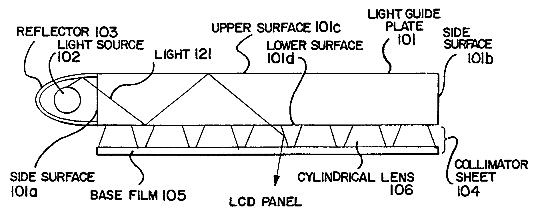
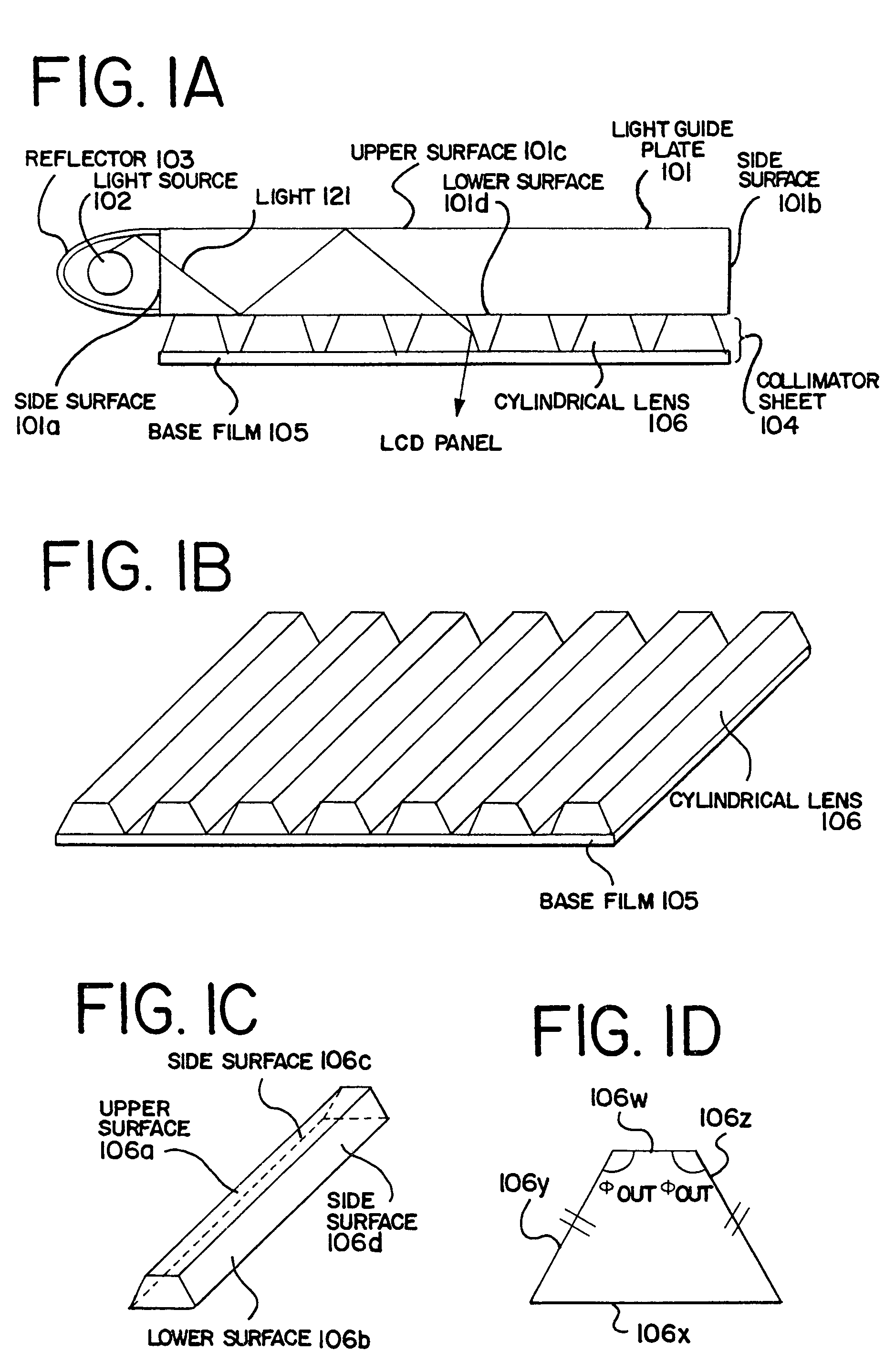
[0053]A front light in the present embodiment utilizes prism-shaped lenses each having an equally-sided trapezoidal cross-section in a plane perpendicular to side surfaces.

[0054]FIG. 1 illustrates a configuration of the front light in the present embodiment. More specifically, FIG. 1A shows a cross-sectional view of the front light, FIG. 1B shows a perspective view of a collimator sheet, FIG. 1C shows a perspective view of each prism-shaped lens, and FIG. 1D shows a cross-sectional view of the prism-shaped lens in a plane perpendicular to the side surfaces.

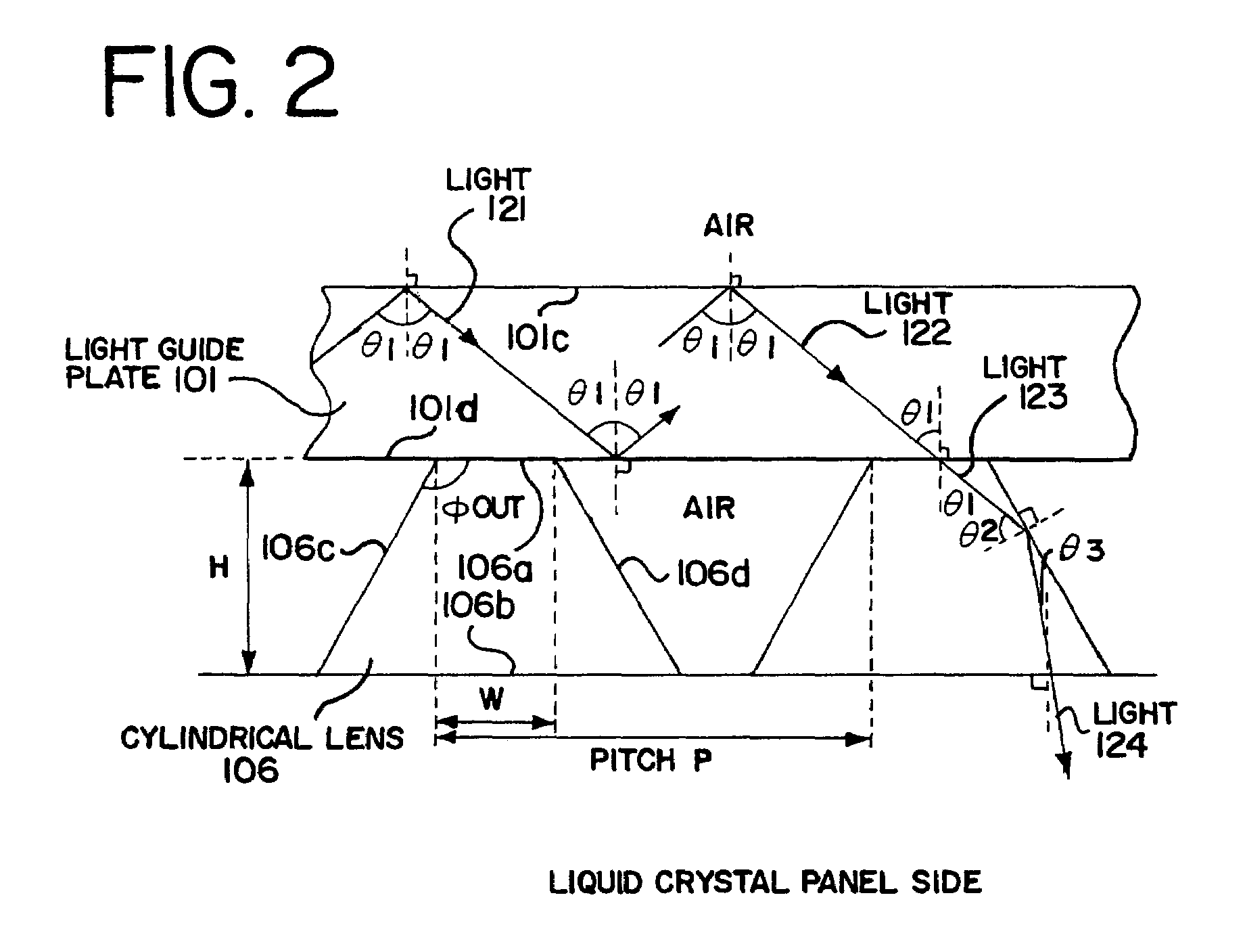
[0055]As shown in FIG. 1A, a light source 102 is disposed on a side surface 101a of a light guide plate 101, and a reflector 103 is further provided behind the light source 102. In addition, a collimator sheet 104 is provided so as to come into contact with a lower surface 101d of the light guide plate 101. For the purpose of clarification of the descriptions, an upper surface 101c of the light guide plate 101 refers to a surface ...

embodiment 2

[0090]In the present embodiment, one modified mode of the prism-shaped lenses in Embodiment 1 will be described. In Embodiment 1, each of the prism-shaped lenses has an equally-sided trapezoidal cross-section. However, as shown in FIGS. 3A to 3C, the light incident on the side surfaces 106c and 106d may transmit therethrough depending on the obtuse angle φout of the equally-side trapezoidal cross-section, thereby resulting in reduced light utilization efficiency. On the other hand, the lenses in the present embodiment are intended to overcome such disadvantages of the prism-shaped lenses having the trapezoidal cross-section, and allow the light incident on the upper surface of the prism-shaped lenses to stop its travel at the side surfaces thereof and be totally reflected therefrom.

[0091]FIG. 6 illustrates a configuration of the front light in the present embodiment. More specifically, FIG. 6A shows a cross-sectional view of the front light, FIG. 6B shows a perspective view of a col...

embodiment 3

[0099]While the prism-shaped lenses are used for the collimator sheet in Embodiments 1 and 2, lenses in the shape of solid of revolution (referred to as the rotational-body lenses in the present specification) are used in the present embodiment. The front light in the present embodiment has the same configuration as that in Embodiment 2, except for the collimator sheet which is a modified mode of that in Embodiment 2. FIGS. 8A and 8B illustrate the configuration of the collimator sheet in the present embodiment.

[0100]As shown in FIG. 8A, rotational-body lenses 306 are provided at equal intervals on a base film 305 made of PET so that an upper surface 306a of each of the rotational-body lenses 306 is in close contact with a lower surface of a light guide plate (not shown in FIG. 8A). The rotational-body lenses 306 and the light guide plate are made of the same material, of course. As shown in FIG. 8B, each of the rotational-body lenses 306 has a shape obtained by rotating an axially-...


PUM

PropertyMeasurementUnit
critical angleaaaaaaaaaa
exiting angleaaaaaaaaaa

Abstract

A front light includes: a light source, a light guide plate, and a plurality of prism-shaped lenses, each being in contact with a lower surface of the light guide plate. A cross-section of each of the prism-shaped lenses, in a plane perpendicular to the side surfaces thereof, has a shape of equally-sided trapezoid. An obtuse angle Φout of the equally-sided trapezoidal cross-section and a critical angle θc for the total reflection of the prism-shaped lenses satisfy the relationship of 90°<Φ out≦90°+θc. When the light emitted from the light source enters the prism-shaped lens, the light is allowed to be reflected at a side surface defined by side-edges of the trapezoidal cross-section and thereafter exit through a lower surface. Thus, the light can illuminate pixel electrodes in a liquid crystal panel from a direction normal thereto.

Description

BACKGROUND OF THE INVENTION[0001]1. Field of the Invention[0002]The present invention relates to a front light to be used for illuminating a reflective liquid crystal panel or the like, and an electronic device including such a front light.[0003]2. Description of the Related Art[0004]Recently, a larger number of portable devices are provided with reflective LCDs (liquid crystal display devices) as display devices for the following reasons. The reflective LCDs utilize external light for displaying an image and thus do not require a back light which is the most power consuming component in the display device. Thus, by using the reflective LCDs, a portable device driven by a battery can be used over a longer period of time. On the other hand, the reflective LCDs have a drawback in which a bright image cannot be displayed when sufficient external light is not available. In such a situation, the displayed image is not recognized well. In order to overcome the above drawback, a front ligh...

Claims


Application Information

Patent Timeline
Patent Type & Authority Patents(United States)
IPC IPC(8): G02B6/34F21V8/00G09F9/00G02B5/02G02B6/00G02F1/1335G02F1/13357
CPCG02B6/0053G02F1/133526G02F1/133615G02B6/0038G02B6/0046G02F2001/133616G02F2001/133607G02B6/0061G02F1/133616G02F1/133607
Inventor KIMURA, HAJIME
Owner SEMICON ENERGY LAB CO LTD
Why Eureka
Try Eureka