
Gas turbine and method for reducing bucket tip shroud creep rate

a technology of gas turbines and shrouds, applied in the field of gas turbines, can solve the problems of partial shroud-to-shroud contact with adjacent buckets, cracks and material losses, and failure to correct damage, so as to reduce the creep rate of bucket tip shrouds

Active Publication Date: 2006-02-21
GENERAL ELECTRIC CO
View PDF18 Cites 17 Cited by
  • Summary
  • Abstract
  • Description
  • Claims
  • Application Information

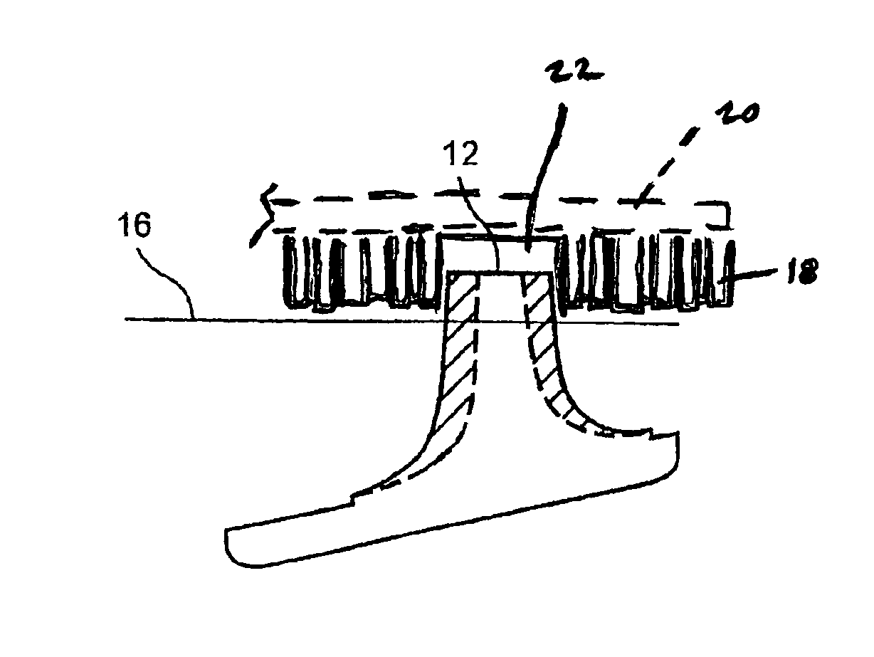
AI Technical Summary

Benefits of technology

"The patent describes a method and apparatus for reducing the creep rate of a bucket tip shroud, which is a part of a turbine. The method involves removing a cutter tooth from the seal rail of the bucket tip shroud, which helps to decrease the creep rate of the seal rail. This can improve the efficiency and lifespan of the turbine."

Problems solved by technology

In certain turbine designs, the bucket tip shrouds, constructed of a nickel-base superalloy, are prone to creep damage that may eventually lead to creep rupture and material loss.
Tip shroud material loss can result in partial shroud-to-shroud contact with adjacent buckets.
Such an occurrence may result in a forced outage, which obviously is disruptive and time-consuming to correct any damage.
Previous designs for bucket tip shrouds have included a scalloped configuration, which configuration helps to reduce the shroud lifting due to creep, but still fails to prevent creep damage at the high stress and high temperature fillet area.

Method used


Image

  • Gas turbine and method for reducing bucket tip shroud creep rate
  • Gas turbine and method for reducing bucket tip shroud creep rate

Examples


Embodiment Construction

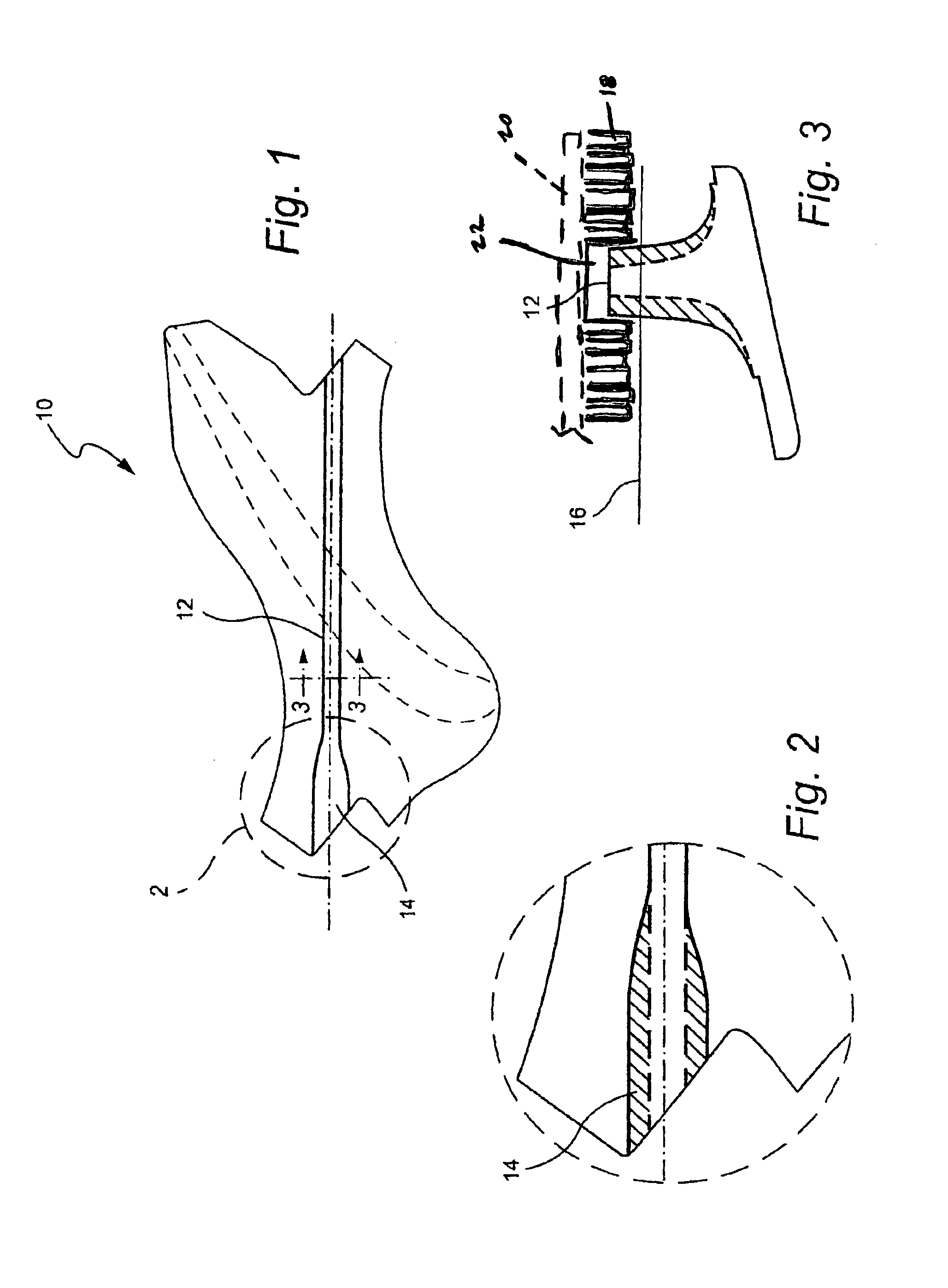
[0009]FIG. 1 shows an exemplary bucket tip shroud 10 including a seal rail 12 with a cutter tooth 14 at one end. FIG. 2 is a close-up view of the cutter tooth 14.

[0010]The present invention utilizes pertinent design information to effect removal of the cutter tooth 14 from the tip shroud rail 12. It has been discovered that by removing the cutter tooth 14, creep rates can be reduced for the component. The cutter teeth removal (repair) extends the bucket shroud creep life and reduces the chance of creep rupture failure which leads to potential forced outage.

[0011]With reference to FIGS. 2 and 3, the cross-hatched area of the cutter tooth 14 is removed from the tip shroud seal rail 12 creating a new seal rail geometry for the bucket. The new resultant configuration maintains the seal rail 12 function and reduces the stress at the shroud by which improves the creep life of the component.

[0012]FIG. 3 details the new shape of the remaining rail 12 from the top of the rail to the upper su...


PUM


Abstract

A bucket tip shroud in a gas turbine includes a seal rail having a cutter tooth at one end. Bucket tip shroud creep rate can be reduced by removing the cutter tooth from the bucket tip shroud seal rail after use or with a pre-groove honeycomb shroud. Preferably, the remaining geometry matches a geometry of the seal rail within a predetermined tolerance.

Description

BACKGROUND OF THE INVENTION[0001]The present invention relates generally to gas turbines and, more particularly, to a gas turbine and method of reducing a bucket tip shroud creep rate by selectively removing cutter teeth on a seal rail of a bucket tip shroud.[0002]In certain turbine designs, the bucket tip shrouds, constructed of a nickel-base superalloy, are prone to creep damage that may eventually lead to creep rupture and material loss. Creep rates in a gas turbine component are determined by the environmental conditions in which the component is placed. Tip shroud material loss can result in partial shroud-to-shroud contact with adjacent buckets. Such an occurrence may result in a forced outage, which obviously is disruptive and time-consuming to correct any damage.[0003]Previous designs for bucket tip shrouds have included a scalloped configuration, which configuration helps to reduce the shroud lifting due to creep, but still fails to prevent creep damage at the high stress a...

Claims


Application Information

Patent Timeline
Patent Type & Authority Patents(United States)
IPC IPC(8): F01D11/08F01D5/00F01D5/14F01D5/20F01D11/12
CPCF01D5/005F01D5/141F01D5/147F01D5/225F01D11/125F05D2260/6022F05B2240/31F05B2240/33F05D2230/80F05D2240/55
Inventor URBAN, JOHN P.MOHR, PATFERNANDEZ, EMILIOKUANG, HUIBERRY, ROBERT R.
Owner GENERAL ELECTRIC CO
Learn More