Hydraulic tensioner

a technology of hydraulic tensioner and spring, which is applied in the direction of gearing, valve arrangement, check valve, etc., can solve the problems of increasing production cost and unable to provide the amount of wear with a time margin, so as to reduce the force exerted on the retainer and prevent over-stressing the spring

Inactive Publication Date: 2006-02-21
TSUBAKIMOTO CHAIN CO
View PDF19 Cites 6 Cited by
  • Summary
  • Abstract
  • Description
  • Claims
  • Application Information

AI Technical Summary

Benefits of technology

[0014]Accordingly, the objects of the present invention are to solve the above-mentioned problems and to provide a hydraulic tensioner, which can prevent the close contact of a spring in an incorporated check valve, can reduce the contact surface pressure between a check ball and a retainer, and can reduce the production cost.
[0016]Since the spring, which biases the check ball onto the ball seat, comprises a conical coil spring in the check valve, bottoming out and over-stressing of the spring can be prevented, reducing forces exerted on the retainer. Further, since the surface of said retainer, which retains the conical coil spring and limits the movement of said check ball is formed of a flat surface or a concave surface, contact pressure between the check ball and the retainer can be further reduced as compared with a conventional case where the movement of the check ball is limited by a protrusion formed in a retainer.

Problems solved by technology

However, hydraulic tensioner 1 has the following problems.
To improve the wear resistance of protrusion 10c, heat treatment is required for increasing the hardness of the surface of the protrusion 10c, which increases the production cost.
However, providing the amount of wear with a time margin was impossible for reasons of molding, strength and limitation of inner diameter of the cylindrical coil spring 9.

Method used


Image

  • Hydraulic tensioner
  • Hydraulic tensioner
  • Hydraulic tensioner

Examples


first embodiment

[0028]a hydraulic tensioner according to the present invention will be described with reference to FIGS. 1 to 5.

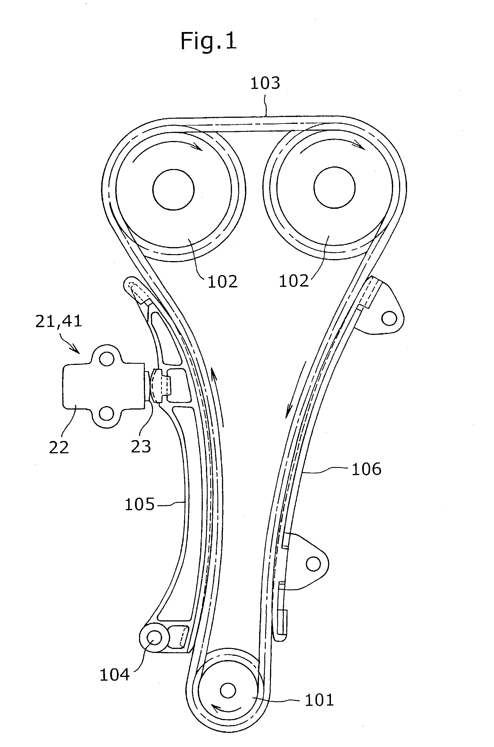
[0029]FIG. 1 is a schematic view showing an example of use of hydraulic tensioners according to first and second embodiments of the present invention.

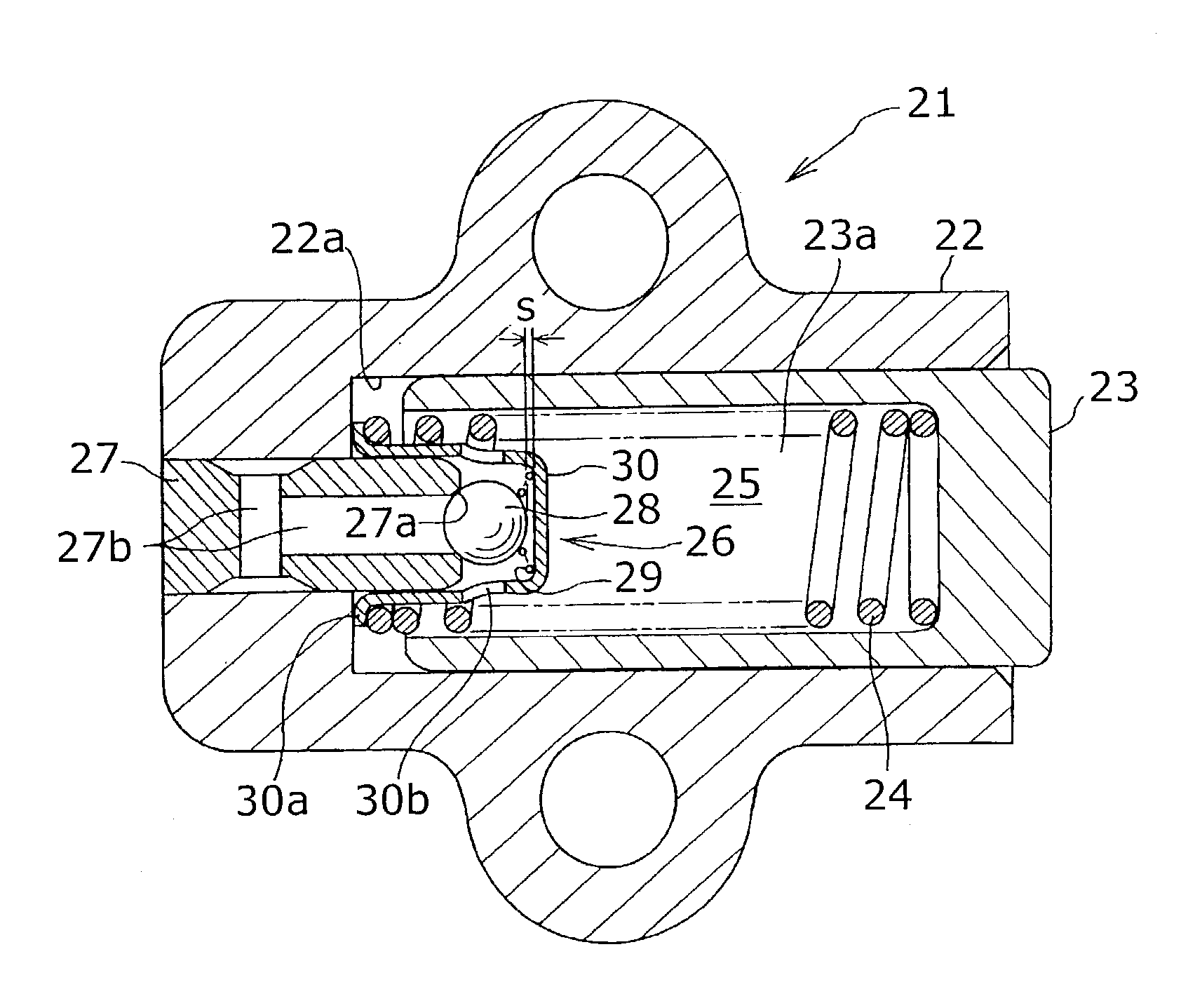
[0030]FIG. 2 is a cross-sectional view of the hydraulic tensioner according to the first embodiment of the present invention.

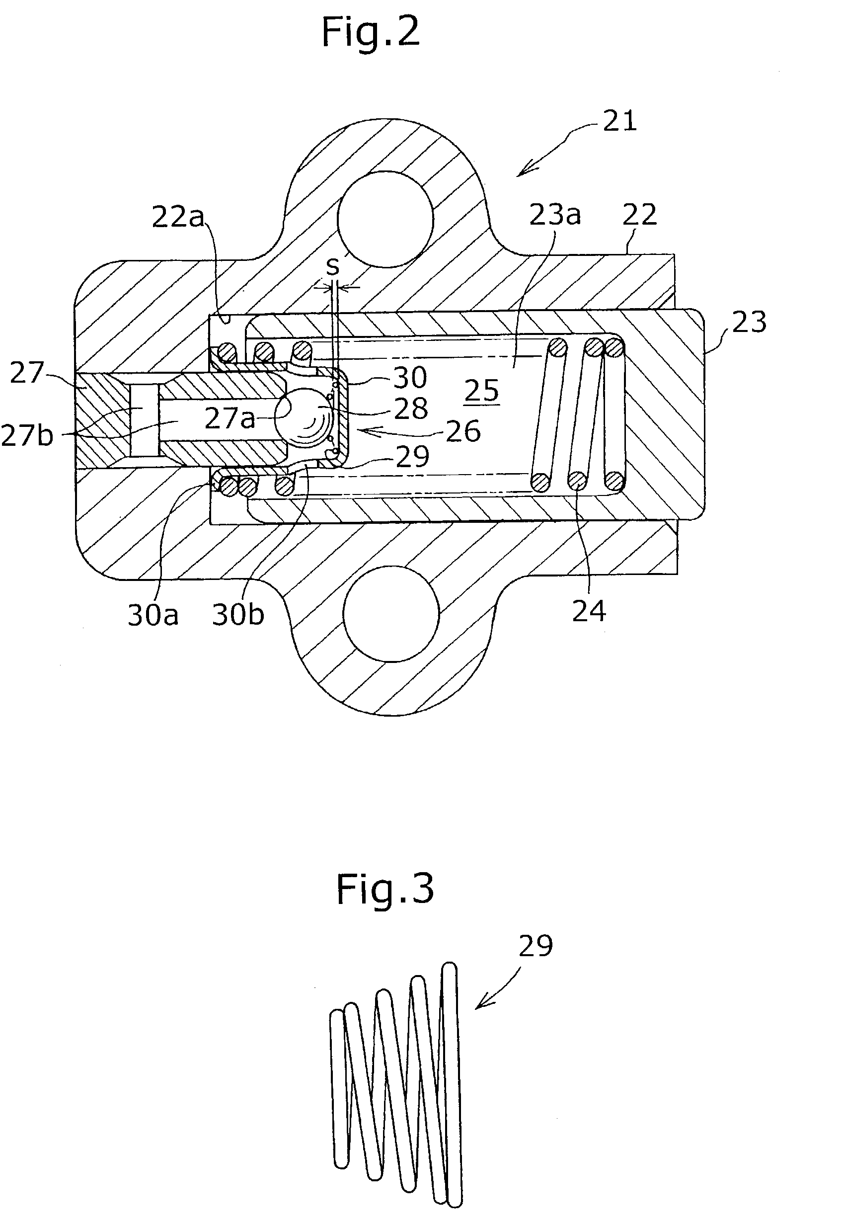
[0031]FIG. 3 is an enlarged view of a conical coil spring forming the check valve in the hydraulic tensioner shown in FIG. 2.

[0032]FIG. 4 is a cross-sectional view showing a state where the check valve of the hydraulic tensioner shown in FIG. 2 is closed. FIG. 5 is a cross-sectional view showing a state where the check valve of the hydraulic tensioner shown in FIG. 2 is opened.

[0033]As shown in FIG. 1, a hydraulic tensioner 21 according to a first embodiment of the present invention is attached to an engine body on a slack side of a chain wrapped between a drive sprocket 101 rotated by a crankshaft of t...


PUM


Abstract

To provide a hydraulic tensioner, which can prevent the bottoming out or over-stressing of a spring in an incorporated check valve, can reduce the contact surface pressure between a check ball and a retainer, and can reduce the production cost, a hydraulic tensioner comprises a check valve incorporated in the housing which causes oil to flow into a high pressure chamber to block the back flow of oil. The check valve comprises a ball seat, a check ball facing the ball seat, a spring, which biases the check ball against the ball seat and a retainer, which retains the spring and limits the movement of the check ball. The spring comprises a conical coil spring, and the surface of the retainer, which retains the conical coil spring and limits the movement of the check ball, is formed in a flat surface.

Description

RELATED APPLICATION[0001]The present application claims priority from Japanese Patent Application No. 2002-049790 filed Feb. 26, 2002.FIELD OF THE INVENTION[0002]The present invention relates to a hydraulic tensioner having a check valve used for applying proper tension to a timing belt or a timing chain or the like in a vehicle engine or the like.BACKGROUND OF THE INVENTION[0003]A hydraulic tensioner has been widely used in a timing belt or a timing chain, which transmits rotation between a crankshaft and a camshaft of a vehicle engine, to suppress vibration generated during displacement of the timing belt or timing chain, and to maintain proper tension. A number of conventional hydraulic tensioners have been proposed which feature a check valve, as disclosed in Japanese Laid-Open Patent Publication No. Hei-11-336855.[0004]FIG. 8 shows an example of such a conventional hydraulic tensioner 1 having a check valve. The hydraulic tensioner 1 is attached to an engine body on a slack sid...

Claims


Application Information

Patent Timeline
Patent Type & Authority Patents(United States)
IPC IPC(8): F16H7/08F16H7/22F16K15/04
CPCF16H7/0848F16H2007/0859F16H2007/0812F16H2007/0806
Inventor HASHIMOTO, HIROSHI
Owner TSUBAKIMOTO CHAIN CO
Why Eureka
Try Eureka