
Switching regulator

a technology of switching regulator and switch, which is applied in the direction of power supply lines, dc-dc conversion, power conversion systems, etc., can solve the problems of high overshoot voltage generation and the danger of damaging devices related to load side output, and achieve the effect of increasing the junction area of emitter-base and driving capability

Active Publication Date: 2006-02-21
ROHM CO LTD
View PDF9 Cites 32 Cited by
  • Summary
  • Abstract
  • Description
  • Claims
  • Application Information

AI Technical Summary

Benefits of technology

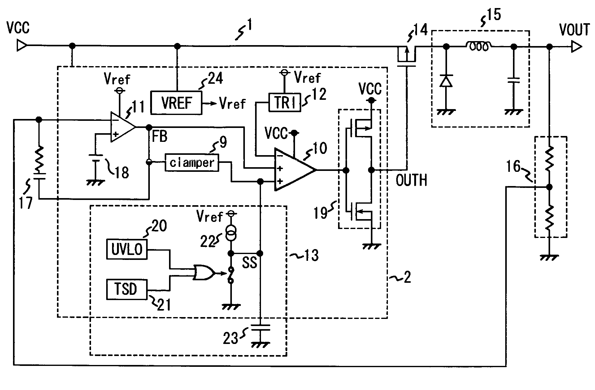
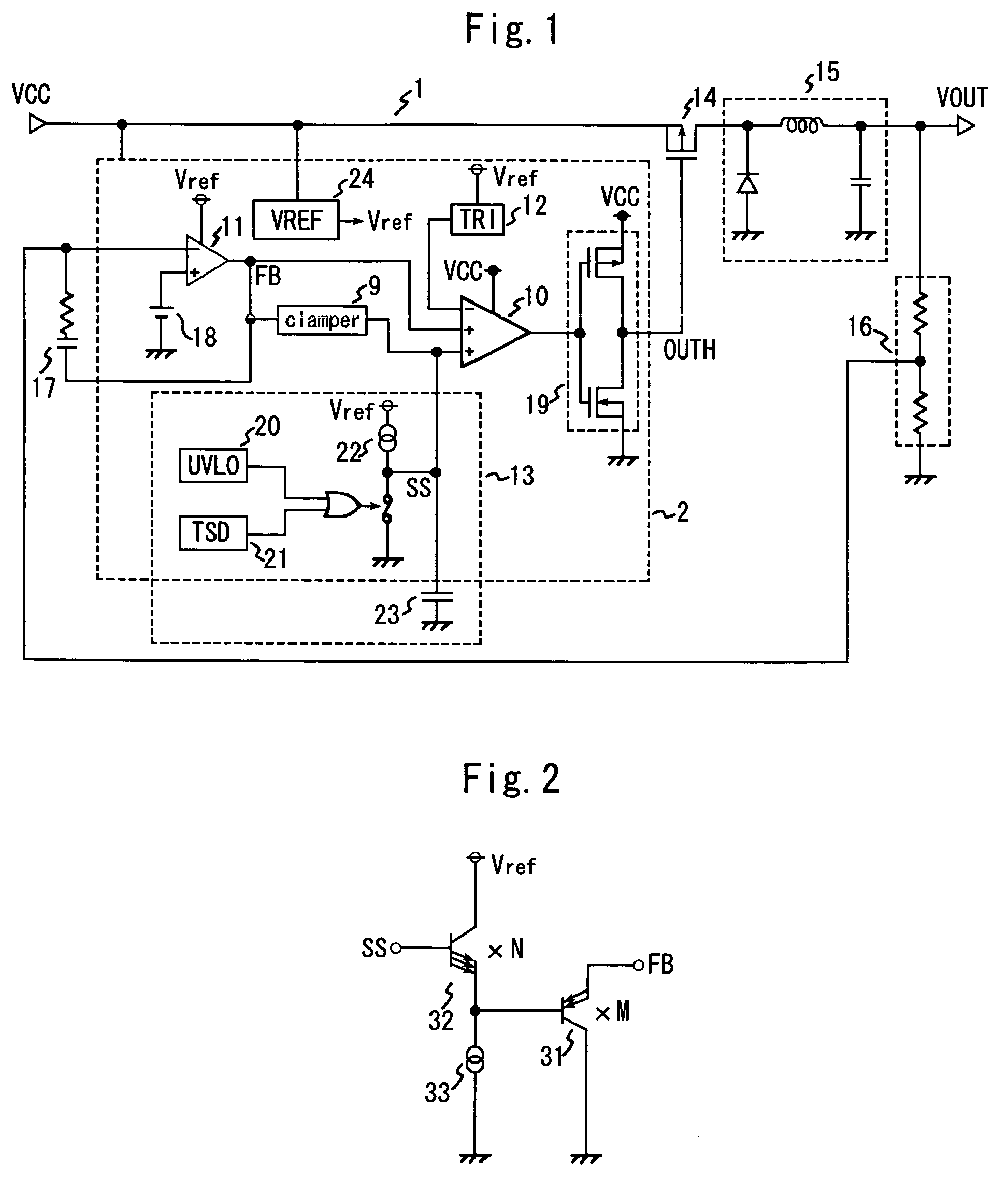
[0016]Since the upper limit value from the output of the soft start circuit to the output of the error amplifier is set by this clamp circuit, the rise of the output voltage of the error amplifier is controlled when power is turned ON, and time until the output of the error amplifier stabilizes can be decreased, and therefore the overshoot voltage to be generated in the load side output is controlled.
[0018]This clamp circuit has a small number of composing elements, so an area occupied by the clamp circuit in a semiconductor integrated circuit can be decreased. Also since the number of composing element is small, the difference of the emitter-base voltages generated by the difference of the emitter-base junction areas can be adjusted relatively simply.
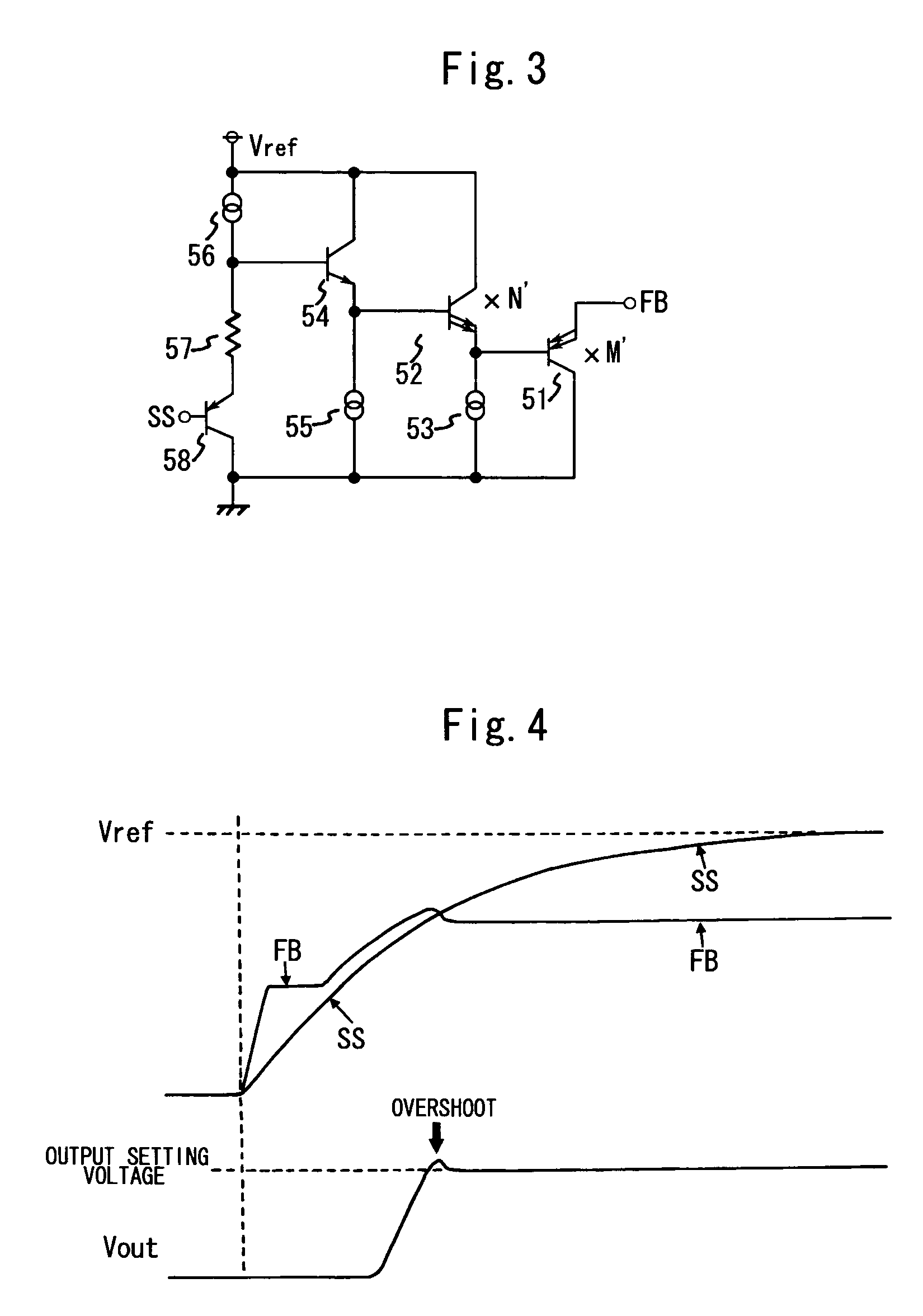
[0020]In this clamp circuit, the voltage generated by the current flowing through the resistor is also included in the factors of setting the clamp voltage, so it is possible to increase the emitter-base junction area of the first transistor, which is related to the output of the error amplifier, and voltage can be sufficiently clamped even if the drive capability of the error amplifier is large.

Problems solved by technology

Along with this, the load side output (VOUT) stabilizes at the output setting voltage, but a high overshoot voltage is generated during this time.
Also this high overshoot voltage has the danger of damaging the devices related to the load side output (VOUT).

Method used


Image

  • Switching regulator
  • Switching regulator
  • Switching regulator

Examples


Embodiment Construction

[0028]Embodiments of the present invention will now be described with reference to the drawings. FIG. 1 is a circuit diagram depicting the configuration of a switching regulator according to an embodiment of the present invention. This switching regulator 1 is composed of basically the same composing elements as those described in the “Description of the Related Art”, to which a later described clamp circuit is added.

[0029]In the switching regulator 1, the switching element 14 supplies power from the power supply side (VCC) to the load side, and holds the load side output (VOUT) at the output setting voltage under a predetermined control by switching, that is according to the output of the later mentioned comparator 10. At the load side of the switching element 14, a smoothing circuit 15, which comprises a coil, a capacitor and a diode, is connected, so as to smooth the voltage from the switching element 14. The load side output (VOUT) is divided by the voltage divider 16 which is c...


PUM


Abstract

The present invention provides a switching regulator for controlling the overshoot voltage which is generated during transition from power ON, when soft start activates, to normal operation, when the load side output is maintained at the output setting voltage by the feedback circuit. A clamp circuit is disposed between a soft start circuit and an error amplifier, an upper limit value from the output of the soft start circuit (SS) to the output of the error amplifier (FB) is set, so that the rise of voltage of the output of the error amplifier (FB) is controlled when power is turned ON, and time until the output of the error amplifier (FB) is stabilized is decreased, by which the overshoot voltage generated in the load side output (VOUT) is controlled.

Description

BACKGROUND OF THE INVENTION[0001]1. Field of the Invention[0002]The present invention relates to a switching regulator for supplying power from the power supply to the load side via a switching element, with which a predetermined voltage at the load side (output setting voltage) can be acquired by switching this switching element under a predetermined control, and more particularly to a switching regulator that has a soft start function.[0003]2. Description of the Related Art[0004]As one system of acquiring output setting voltage, a switching regulator system, which switches a switching element under a predetermined control, has been conventionally used since it is compact and can implement high efficiency. In order to control rush current which flows into the switching element when power is turned ON, a soft start operation is executed (e.g. Japanese Patent Application Laid-On No. 7-336999).[0005]FIG. 6 is a circuit diagram of a conventional switching regulator. In the switching re...

Claims


Application Information

Patent Timeline
IPC IPC(8): G05F1/40H02M3/156H02M3/155
CPCH02M1/36H02M3/156Y10S323/901H02M3/155
Inventor KITANI, HIROSHIUMEKI, NOBUAKI
Owner ROHM CO LTD
Learn More