Rotation angle detecting device

a detection device and rotating angle technology, applied in galvano-magnetic devices, galvano-magnetic hall-effect devices, instruments, etc., can solve problems such as and achieve the effect of preventing the deterioration of the precision of the detection of angles

Inactive Publication Date: 2006-02-21
DENSO CORP +1
View PDF8 Cites 21 Cited by
  • Summary
  • Abstract
  • Description
  • Claims
  • Application Information

AI Technical Summary

Benefits of technology

[0012]Considering the foregoing problems, an object of the present invention is to provide a rotation angle detecting device in which precision in the detection of an angle is prevented from deteriorating even when there is a slight misalignment (assembly error) between first and second magnetic sensors, and hysteresis does not occur in the output characteristics of the first and second magnetic sensors.
[0013]In one aspect of the present invention, a rotation angle detecting device includes a magnetic flux concentrator disposed in parallel with a magnet, and first and second magnetic sensors disposed between the peripheral circle of the magnet and the peripheral circle of the magnetic flux concentrator. Thus, the magnetic flux concentrator regulates lines of magnetic flux applied from the magnet to the first and second magnetic sensors. Therefore, if there is a slight misalignment (assembly error) in the first and second magnetic sensors, the vector components of magnetic flux applied to the magnetically sensitive surfaces of the first and second magnetic sensors are prevented from varying. In other words, if there is an assembly error in the first and second magnetic sensors, it is possible to prevent precision in the detection of an angle from deteriorating.
[0014]Since the magnet and the magnetic flux concentrator integrally rotate, hysteresis does not occur in the output characteristics of the first and second magnetic sensors in the first and latter halves of the rotation (the forward rotation and the reverse rotation) of the magnet. Therefore, it is possible to eliminate deterioration in precision in the detection of an angle due to hysteresis.

Problems solved by technology

Accordingly, precision in the detection of an angle becomes worse.

Method used


Image

  • Rotation angle detecting device
  • Rotation angle detecting device
  • Rotation angle detecting device

Examples


first embodiment

[0043]A first embodiment will now be described with reference to FIGS. 1A to 4B.

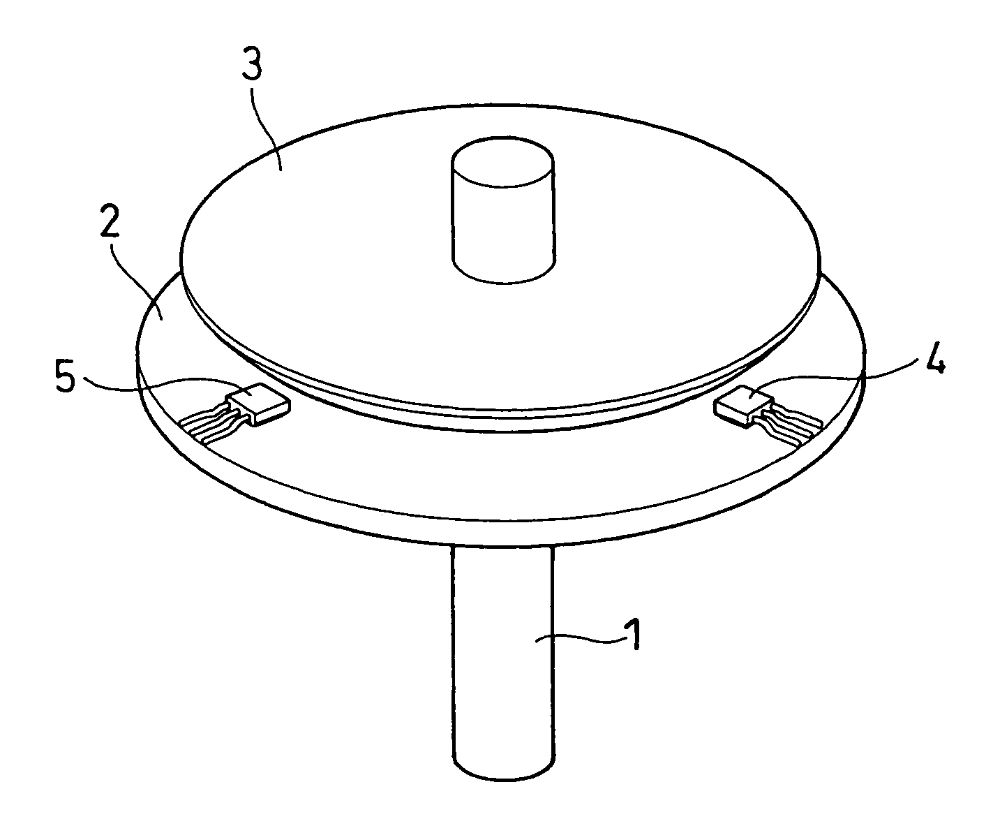
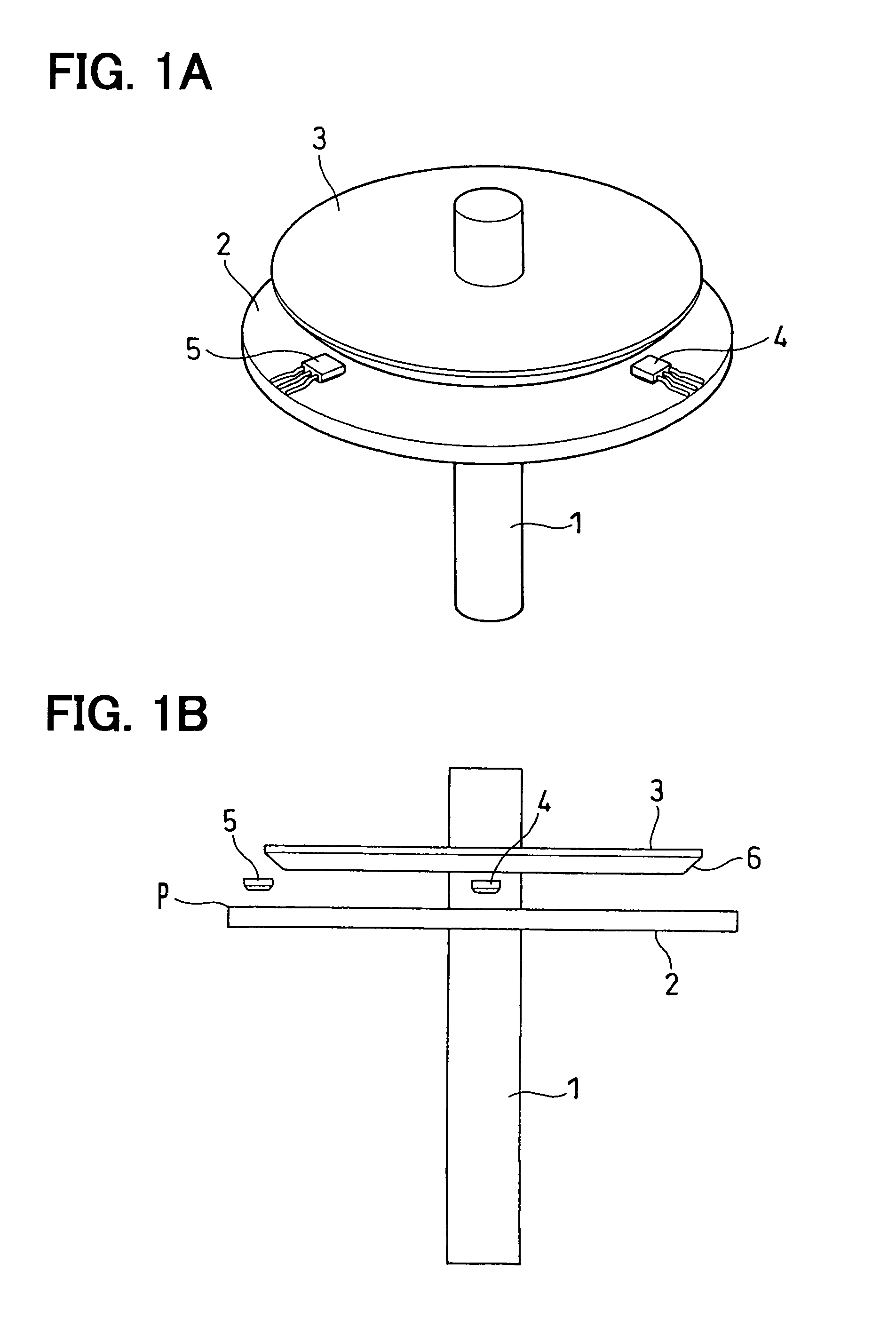
[0044]Referring to FIGS. 1A and 1B, the fundamental structure of a rotation angle detecting device will be first described. FIG. 1A is a schematic perspective view of the rotation angle detecting device, and FIG. 1B is a schematic side view thereof.

[0045]The rotation angle detecting device according to the first embodiment comprises a rotational axis 1, a magnet 2, a magnetic flux concentrator 3, and first and second magnetic sensors 4 and 5. The rotational axis 1 rotates integrally with a rotary member (for example, a throttle valve), the rotation angle of which is detected. The magnet 2 and the magnetic flux concentrator 3 rotate integrally with the rotational axis 1. The first and second magnetic sensors 4 and 5 are secured to a fixed member (for example, a substrate secured to a throttle housing).

[0046]The magnet 2 is a permanent magnet which is secured to the rotational axis 1 and rotates integrally...

third embodiment

[0068]A third embodiment will now be described with reference to FIG. 6.

[0069]A first chip 7, in which two first magnetic sensors 4 are enclosed, is disposed in a position in which the first magnetic sensor 4 according to the foregoing first embodiment is disposed. One of the first magnetic sensors 4 has the magnetically sensitive surface which is oriented in the axial direction of the rotational axis 1, and the other of the first magnetic sensors 4 has the magnetically sensitive surface which is oriented in one of the radial directions of the rotational axis 1. The outputs of the two first magnetic sensors 4 are averaged to be used in angle calculation.

[0070]A second chip 8, in which two second magnetic sensors 5 are enclosed, is disposed in a position in which the second magnetic sensor 5 according to the foregoing first embodiment is disposed. One of the second magnetic sensors 5 has the magnetically sensitive surface which is oriented in the axial direction of the rotational axi...


PUM


Abstract

A rotation angle detecting device includes a magnet, a magnetic flux concentrator, a first magnetic sensor, and a second magnetic sensor. The magnet is provided in a rotary member and is substantially coaxially aligned with a rotational axis thereof. The magnet has a magnetic flux generation section and a magnetic flux absorption section oriented in radial directions vertical to the rotational axis. The magnetic flux concentrator is made of a magnetic material and rotates integrally with the magnet. The magnetic flux concentrator is substantially coaxially aligned with the rotational axis and disposed substantially parallel to the magnet. The first and second magnetic sensors are disposed between the magnet and the magnetic flux concentrator at a predetermined angle away from each other in a rotational direction. The rotation angle detecting device detects the rotation angle of the rotary member based on magnetic flux passing through the first and second magnetic sensors.

Description

CROSS REFERENCE TO RELATED APPLICATIONS[0001]This application is based upon and claims the benefit of priority of Japanese Patent Application No. 2004-162249, filed on May 31, 2004, the contents of which are incorporated herein by reference.FIELD OF THE INVENTION[0002]The present invention relates to a rotation angle detecting device which detects the rotation angle of a rotary member without contact.BACKGROUND OF THE INVENTION[0003]A technology shown in FIG. 7 is known as a rotation angle detecting device which detects a wide range of rotation angles by use of a magnet and a magnetic sensor.[0004]This rotation angle detecting device comprises a magnet 2 formed in the shape of a disc, a first magnetic sensor 4, and a second magnetic sensor 5. The center of the peripheral circle of the magnet 2 is coaxial with a rotational axis. In the magnet 2, a magnetic flux generation section is oriented in one of radial directions vertical to the rotational axis, and a magnetic flux absorption s...

Claims


Application Information

Patent Timeline
Patent Type & Authority Patents(United States)
IPC IPC(8): G01B7/30G01D5/245G01D5/14G01P3/48G01P3/54
CPCG01D5/145
Inventor KAWASHIMA, TAKASHITAKEDA, KENJI
Owner DENSO CORP
Why Eureka
Try Eureka