Domino logic compatible scannable flip-flop

Inactive Publication Date: 2006-02-21
STMICROELECTRONICS SRL
View PDF4 Cites 11 Cited by
  • Summary
  • Abstract
  • Description
  • Claims
  • Application Information

AI Technical Summary

Benefits of technology

[0012]The invention discloses several new circuits based on scannable flip-flop designs that may be used for driving domino logic circuits. In order to interface with a domino circuit,

Problems solved by technology

Domino logic is faster than standard static logic, but it is more difficult to design because of its increased complexity, primarily in the clocking network.
The hysteresis increases the delay through the circuit and the short circuit current power consumed by the circuit.
However, an output glitch occurs if both the output and data input are at logical high values when the clock

Method used


Image

  • Domino logic compatible scannable flip-flop
  • Domino logic compatible scannable flip-flop
  • Domino logic compatible scannable flip-flop

Examples


embodiment 80

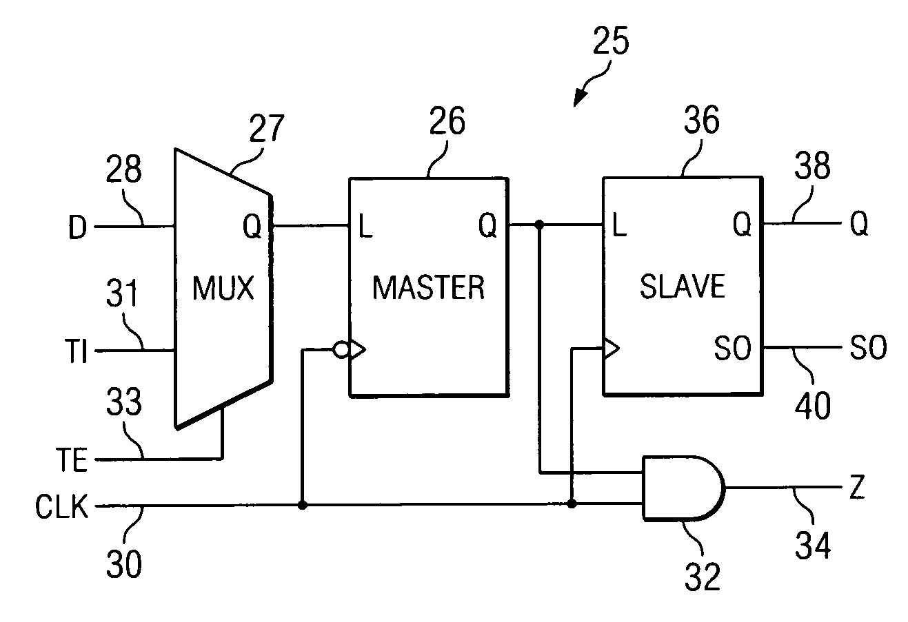
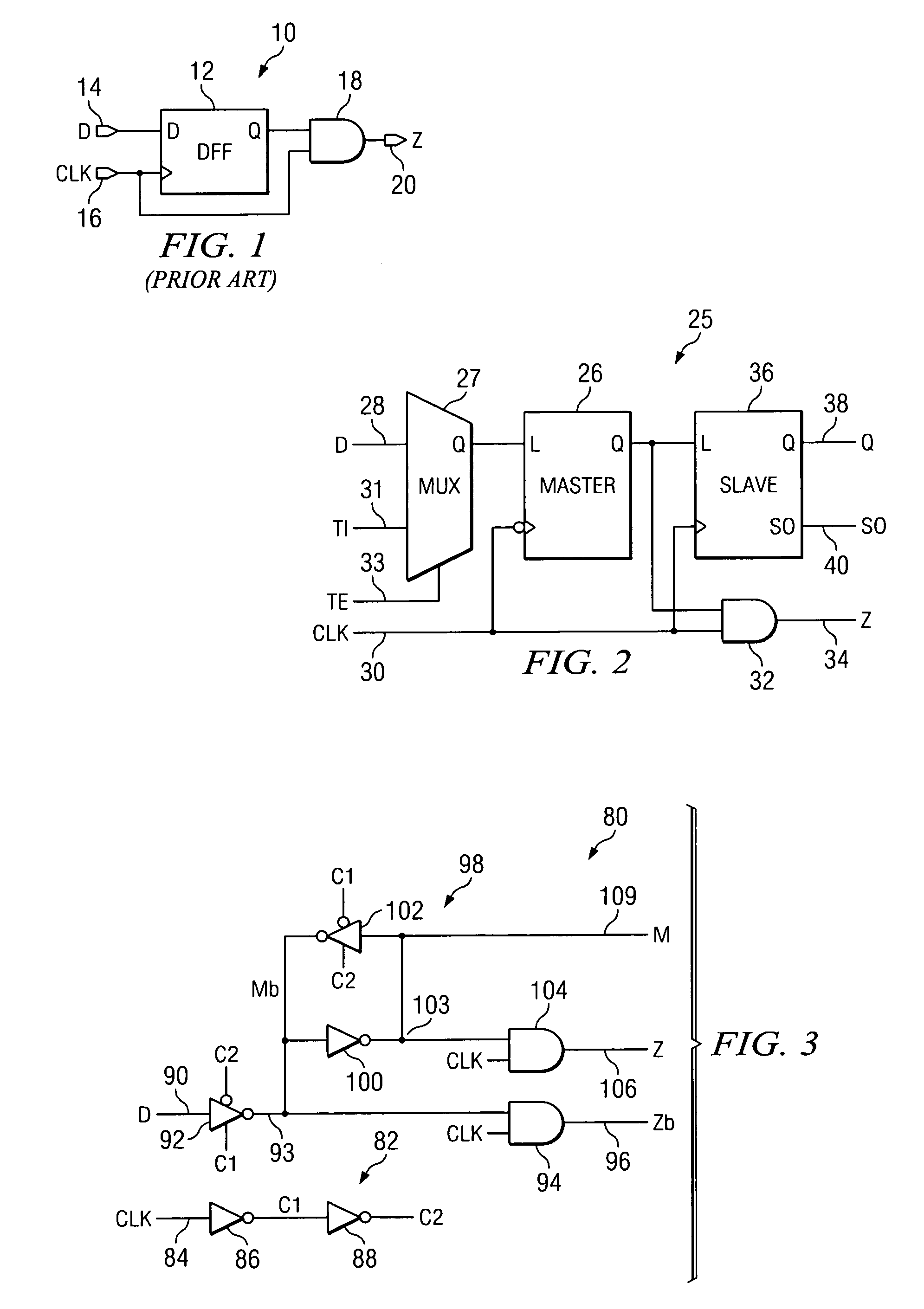
[0030]FIG. 3 is an electrical schematic diagram of a latch circuit embodiment 80 having both domino and static test outputs, according to a preferred embodiment of the invention. The circuit 80 has domino outputs, denoted Z and Zb, where Zb is the logical signal inverse of Z; however, both Z and Zb go low when the clock signal goes low. The circuit 80 can be used to implement the master latch 26 and the AND gate 32 in circuit 25 shown in FIG. 2.

[0031]The circuit 80 is clocked by clock signals C1 and C2 provided by clock generator 82. The clock generator 82 receives original clock signals, Clk, on input line 84 to inverter 86, to generate clock signal C1, which is applied to an inverter 88, which generates clock signal C2. Clock signals C1 and C2 are, therefore, out of phase by 180 degrees.

[0032]The circuit 80 has a data input, D, on line 90 to an tristate inverter 92 that is clocked by both clock signals C1 and C2 to generate an output on line 93. The signal on line 93 is compared w...

embodiment 45

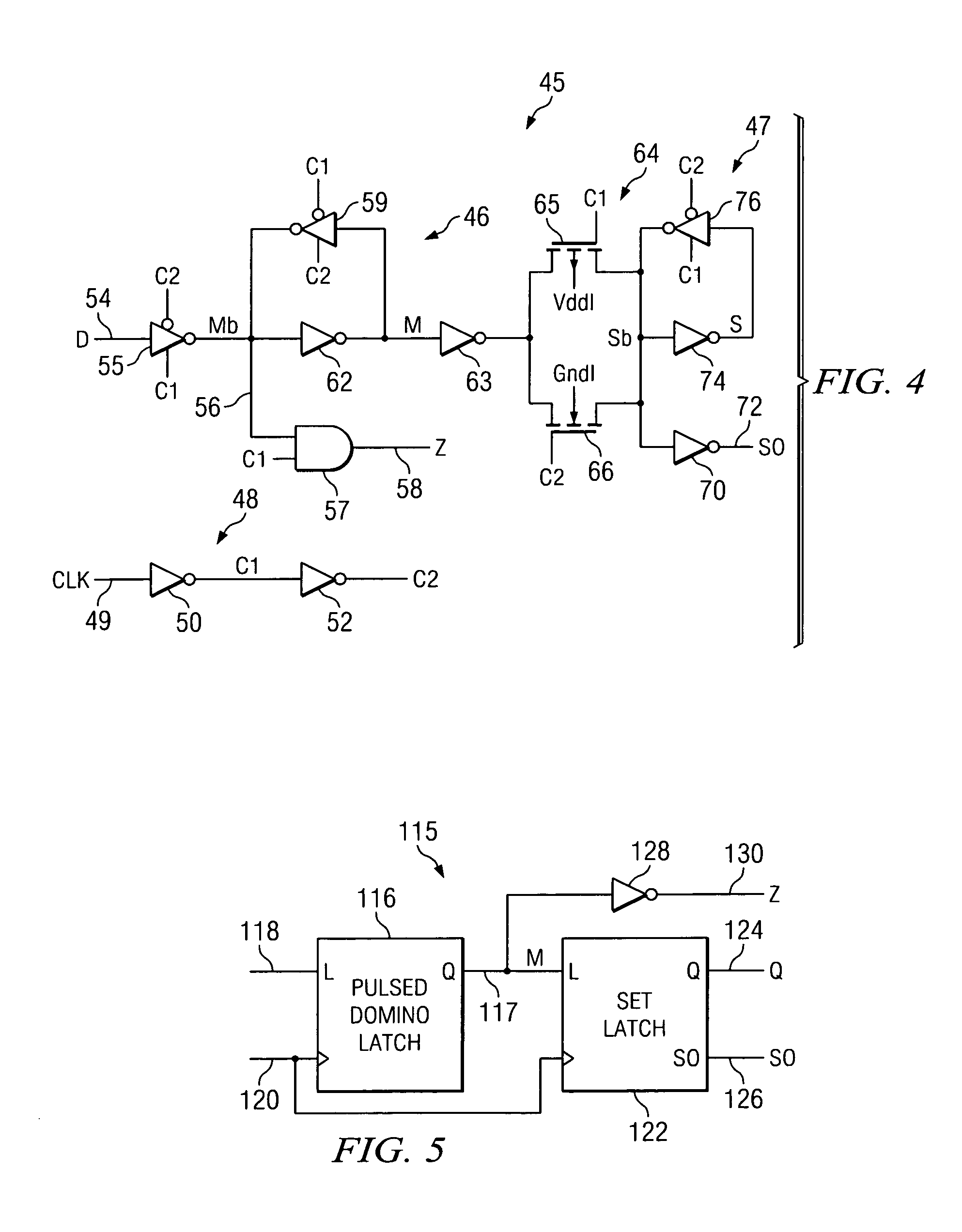
[0034]An additional domino latch circuit embodiment 45 is shown in FIG. 4, to which reference is now additionally made. The circuit 45 represents an implementation of master latch 26, the slave latch 36 and the AND gate 32 in circuit 25 shown in FIG. 2. The circuit 45 includes a local clock generator 48, which receives an original clock signal input, Clk, on line 49. The local clock generator 48 serves to generate out of phase clock signals C1 and C2 at the respective outputs of inverters 50 and 52.

[0035]Data, D, is received on input line 54, and is clocked into the circuit by tristate inverter 55, which is clocked by both clock signals C1 and C2. The data output from inverter 55 on line 56 is then compared by AND gate 57 to the original clock signal, Clk, to provide a domino output on line 58.

[0036]Keeper circuits 46 and 47 are utilized as the latching mechanisms within the circuit 45, and are used to statically hold test data when the circuit is operated in a test mode of operatio...


PUM


Abstract

A testable, prechargeable circuit has a driving circuit for producing a driving circuit output signal. A timing circuit receives a clock signal and the driving circuit output signal to cause an output of the testable, prechargeable circuit to be in a low state when the clock signal is low. The timing circuit also causes the output of the circuit to be timed with a state change in the clock signal to provide a domino logic output signal. Either a data signal or a test signal are multiplexed to the input of the driving circuit to produce respectively the domino logic output signal or a test output signal. A static logic circuit receives the test output signal to produce a test signal output.

Description

BACKGROUND OF INVENTION[0001]1. Field of Invention[0002]This invention relates to improvements in logic circuits and techniques, and more particularly to improvements in logic circuits and techniques that are compatible with domino logic circuit structures, and still more particularly to improvements in logic circuits and techniques of the type described that are scannable for circuit testing.[0003]2. Background of Invention[0004]Recently, domino logic circuits and design have been receiving the attention of logic circuit designers and fabricators. Domino logic is a precharged, non-inverting family of Complementary Metal Oxide Silicon (CMOS) logic that uses multiple clock phases to effect high-speed operation. Domino logic is faster than standard static logic, but it is more difficult to design because of its increased complexity, primarily in the clocking network.[0005]Typically in domino logic, at least a “precharge” clock phase is used, followed by an “evaluate” clock phase. Duri...

Claims


Application Information

Patent Timeline
IPC IPC(8): H03K19/096G01R31/3185H03K19/173
CPCG01R31/318541
Inventor ANDERSON, SCOTT B.HOSSAIN, RAZAKZOUNES, THOMAS D.
Owner STMICROELECTRONICS SRL
Why Eureka
Try Eureka