Method and apparatus to improve SCDMA headroom

a headroom and headroom technology, applied in transmission systems, transmission systems, television systems, etc., can solve the problems of insufficient power output of the transmitter in the more remote cable modem, the loss of the cable plant, and the inability to get the transmission through to the headend modem

Active Publication Date: 2006-02-21
AVAGO TECH INT SALES PTE LTD
View PDF5 Cites 51 Cited by
  • Summary
  • Abstract
  • Description
  • Claims
  • Application Information

AI Technical Summary

Benefits of technology

[0013]This technique of fragmenting bursts into smaller segments which require a smaller number of codes calculated to solve the headroom problem efficiently increases the received power per code from each modem with a headroom problem without a physical modification of the modem's transmitter.

Problems solved by technology

Certain cable plants are so lossy that cable modems in remote positions on the network, even when using maximum transmit power, cannot get their transmissions through to the headend modem.
However, in very lossy systems, some transmitters in the more remote cable modems cannot output enough power to achieve the desired signal power level at the CMTS modem even when their transmit amplifiers are set to maximum transmit power.
This causes problems for the CMTS modem, because it does not receive the burst it was expecting from each of these remote modems and some will be outside the range of the AGC and will not be using the full dynamic range of the A / D converter.
Nothing can be done at the remote modem to remedy the problem because the gain of the transmit amplifiers of the remote modems that are having the problem is already set to maximum power.
Likewise, nothing can be done at the CMTS modem to remedy the problem since neither the dynamic range of the A / D converter nor the gain controlled range of the CMTS receiver can be changed, so signals with insufficient power will not use the full dynamic range of the A / D converter and will be outside the automatic gain control's ability to control the amplitude of the signal.
Nothing can be easily done to lessen the losses in the HFC network.

Method used


Image

  • Method and apparatus to improve SCDMA headroom
  • Method and apparatus to improve SCDMA headroom
  • Method and apparatus to improve SCDMA headroom

Examples


Embodiment Construction

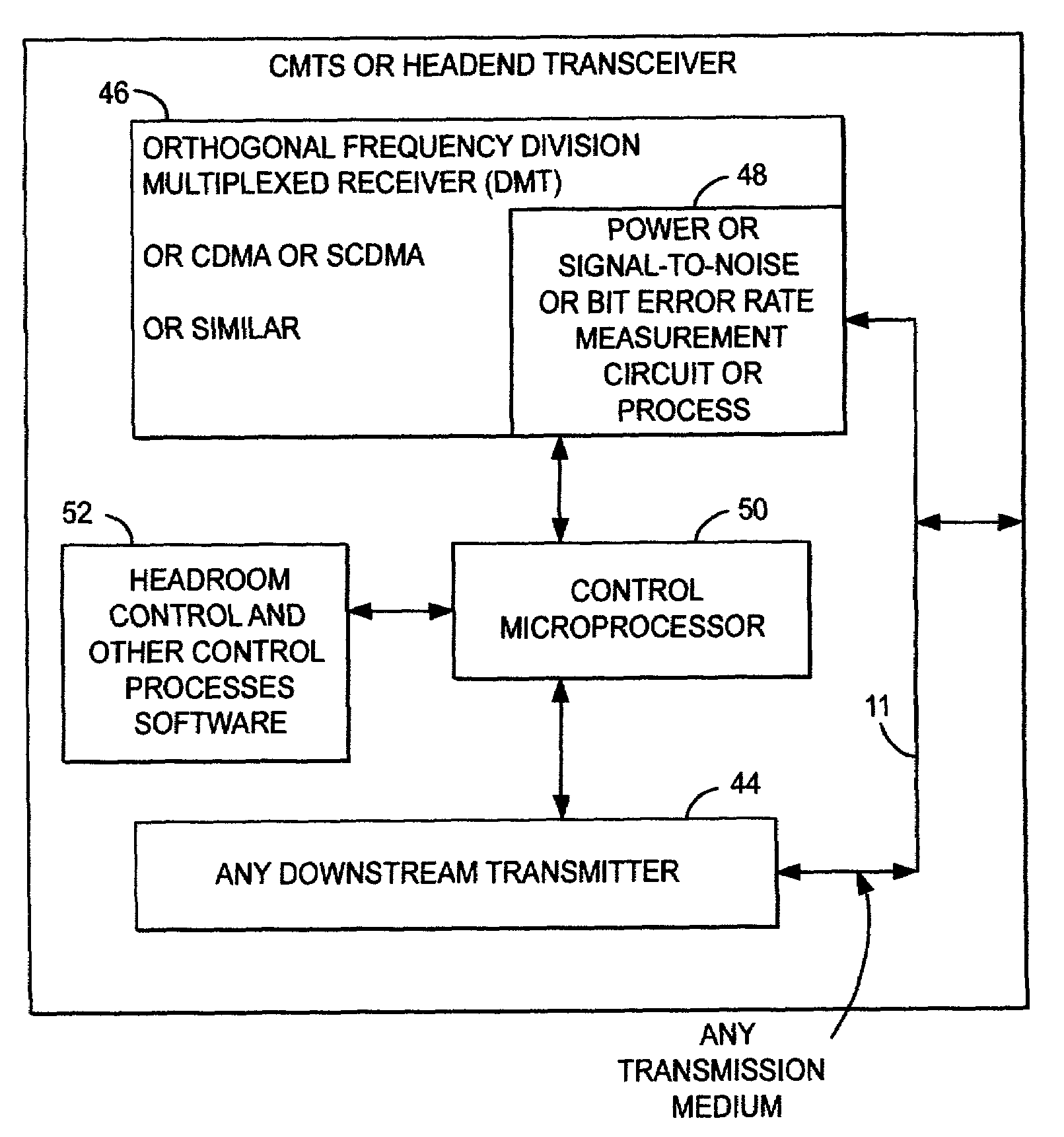
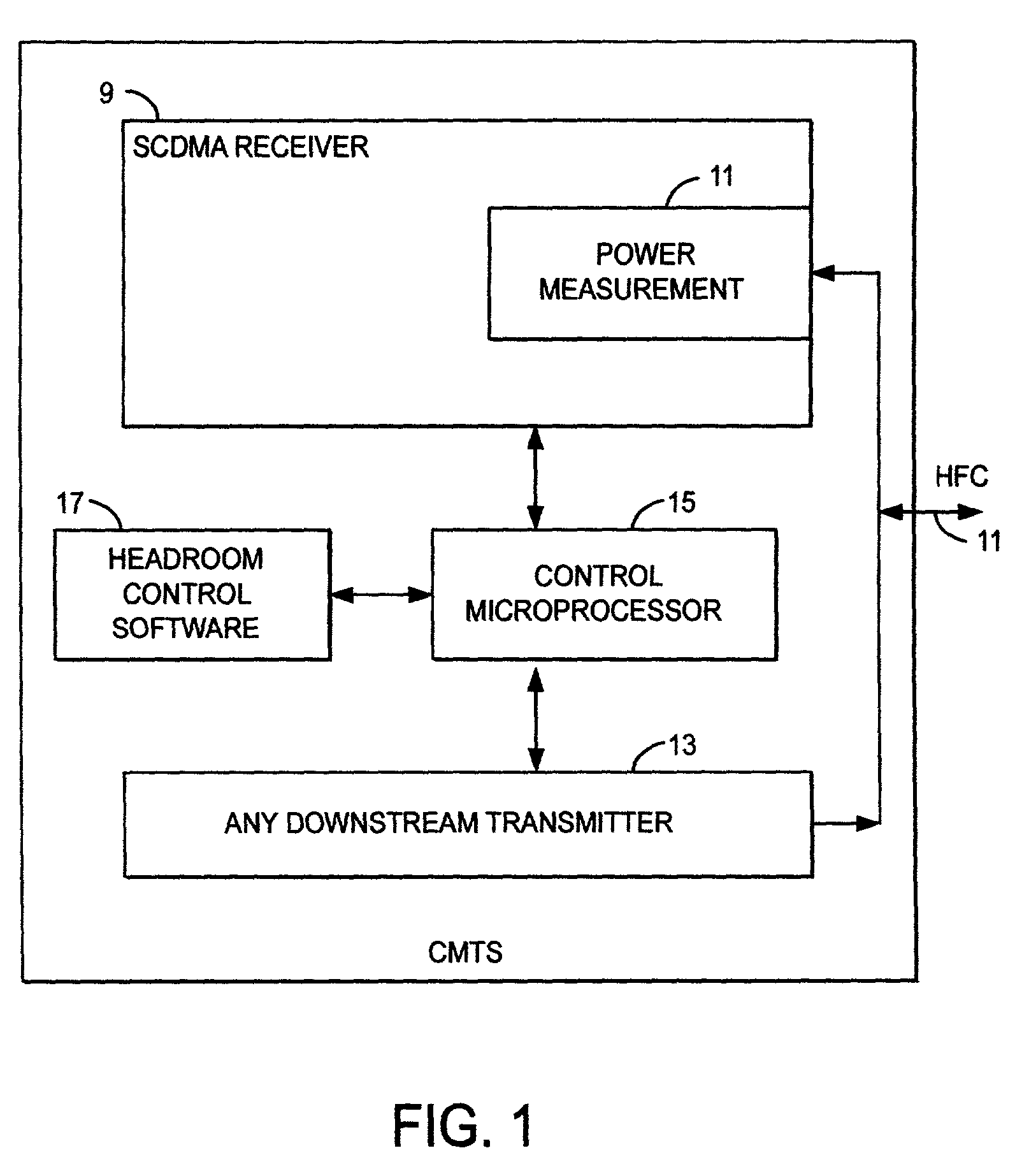
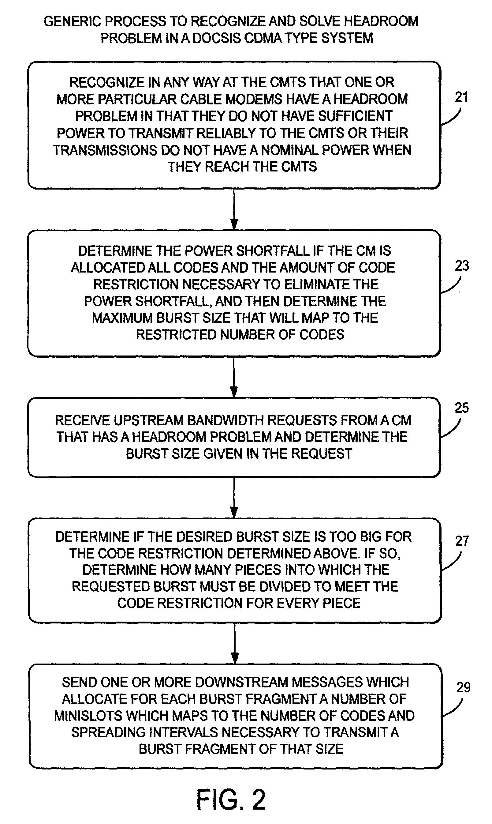
[0019]Spreading the spectra of data by code division multiple access causes the power of a burst to be spread out over time and over the allocated bandwidth. This is because, in contrast with TDMA when the entire symbol is transmitted in one symbol time, in CDMA, each symbol is transmitted over a large number of chip clock cycles where the chip clock is running much faster than the symbol clock. This spreads the spectrum of the symbol, but results in less power being transmitted during any particular interval. Thus, over any particular interval of time, less power is received with the spread spectrum signal than would have been received had the original burst not been spread although the total energy received if the power is integrated over time would be the same. If more chips are used per symbol, less power can be used to transmit a symbol and it will still get through.

[0020]With multiple remote transceivers all transmitting over a shared media to a single CMTS headend transceiver...


PUM


Abstract

A method of determining when cable modems in a distributed digital data delivery service over cable TV hybrid fiber coaxial cable network have a headroom problem and resolving said problem. The method involves measuring the burst power from each cable modem, and if the burst power is too low, requesting the cable modem whose burst power is too low to increase its transmit power, and keeping track of which modems have been requested to increase their power. If a predetermined number of requests to increase power have not resulted in the cable modem transmitting with sufficient power for reliable reception, the cable modem is listed as having a headroom problem. Subsequent requests for upstream bandwidth from all modems with headroom problems are analyzed to determine if the requested burst size is too large and will result in a headroom problem. If so, a calculation as to the maximum number of spreading codes that each modem with a headroom problem can simultaneously transmit on without a headroom problem. The requested burst is then broken down into smaller burst fragments, and appropriate upstream minislot assignments adequate to transmit the burst fragments are made and sent to the cable modem.

Description

BACKGROUND OF THE INVENTION[0001]Certain cable plants are so lossy that cable modems in remote positions on the network, even when using maximum transmit power, cannot get their transmissions through to the headend modem.[0002]The Cable Modem Termination System (hereafter CMTS) wants to receive bursts from all the remote modems at approximately the same power level regardless of where on the HFC network the modem resides. To accomplish this end, the CMTS receiver in DOCSIS systems for digital data delivery over hybrid fiber coax controls the power of transmissions by each remote modem by a downstream message to each modem. The CMTS controls the power level of transmissions to it by the remote modems so as to keep the received power of each burst at the CMTS within the gain controlled range of the CMTS receiver so as to not saturate its A / D converter and so as to use the full dynamic range of the A / D converter. However, in very lossy systems, some transmitters in the more remote cabl...

Claims


Application Information

Patent Timeline
Patent Type & Authority Patents(United States)
IPC IPC(8): H04J11/00H04J13/00H04L27/26H04N7/173
CPCH04N7/17309H04J13/16H04L5/0016H04L25/0226H04L5/0048
Inventor AZENKOT, YEHUDARAKIB, SELIM SHLOMO
Owner AVAGO TECH INT SALES PTE LTD
Why Eureka
Try Eureka