
Distributed soft handoff among IP-based base stations

a technology of soft handoff and base station, which is applied in the field of wirelesstowireline and wirelesstowireless communication system, can solve the problems of incompatible systems co-existing, difficult to roam from one system to another, and no wireless technology has emerged as a common and long-term universal solution

Active Publication Date: 2006-02-21
TELCORDIA TECHNOLOGIES INC
View PDF6 Cites 39 Cited by
  • Summary
  • Abstract
  • Description
  • Claims
  • Application Information

AI Technical Summary

Benefits of technology

"The present invention provides a method and system for transmitting packets to a mobile station from a wireline subnet through base stations. The method involves assigning an alias or shadow address to the mobile station and storing it in the base stations during soft handoff. The system includes a generator for generating link layer frames with compatible shadow addresses and means for filling in the frames with packets starting with the same one in each base station. The result is a matchable stream of packets delivered to the mobile station from two different base stations. The technical effects of this invention include improved reliability and stability during handoff and more efficient delivery of packets to the mobile station."

Problems solved by technology

Generally, the numerous wireless systems are not compatible with each other, making it difficult to roam from one system to another.
Although there have been attempts to unify third-generation wireless systems, incompatible systems are expected to co-exist in the future.
So far, no wireless technology has emerged as a common and long-term universal solution.
There are, however, many challenges to realizing distributed all-IP wireless networks.
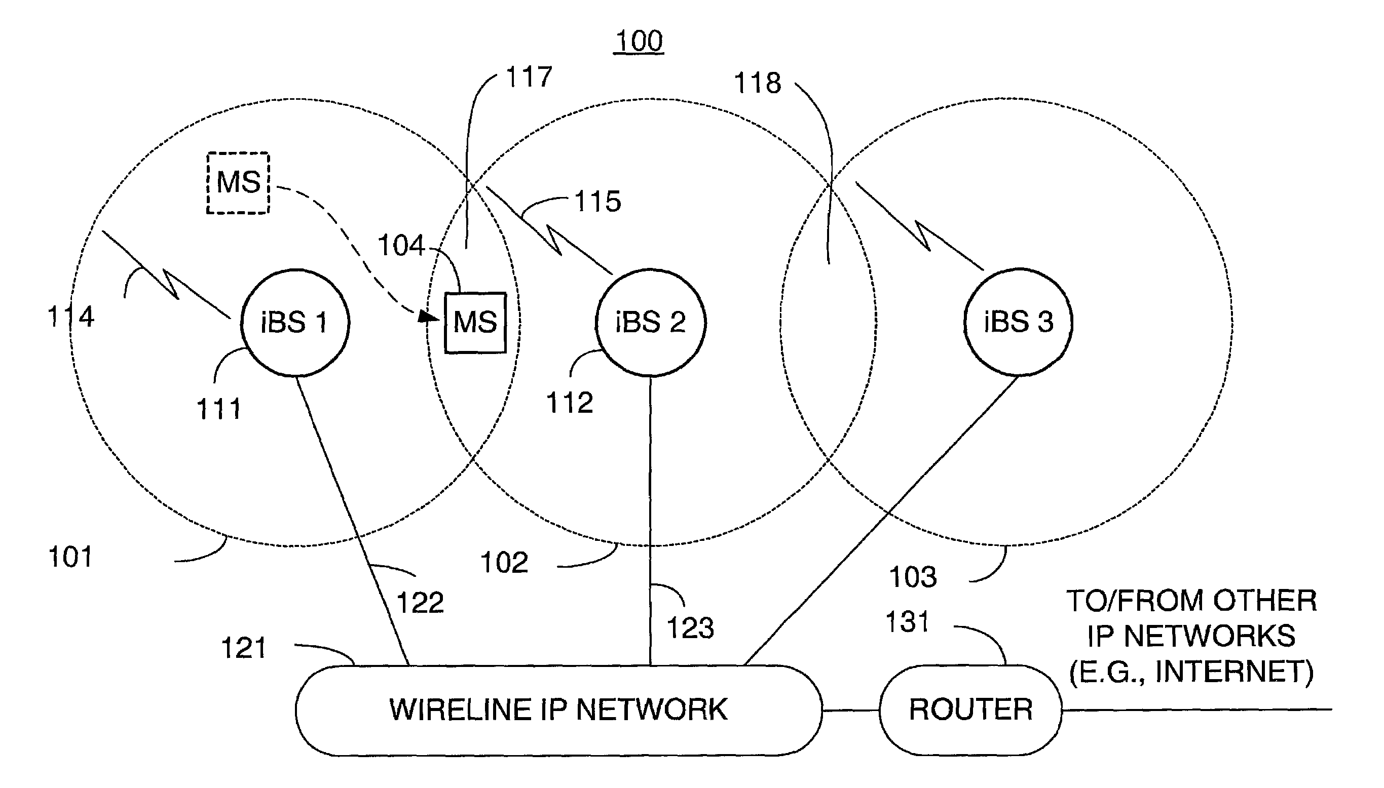
Among the key challenges in a distributed all-IP wireless network is how to support “soft handoff”.
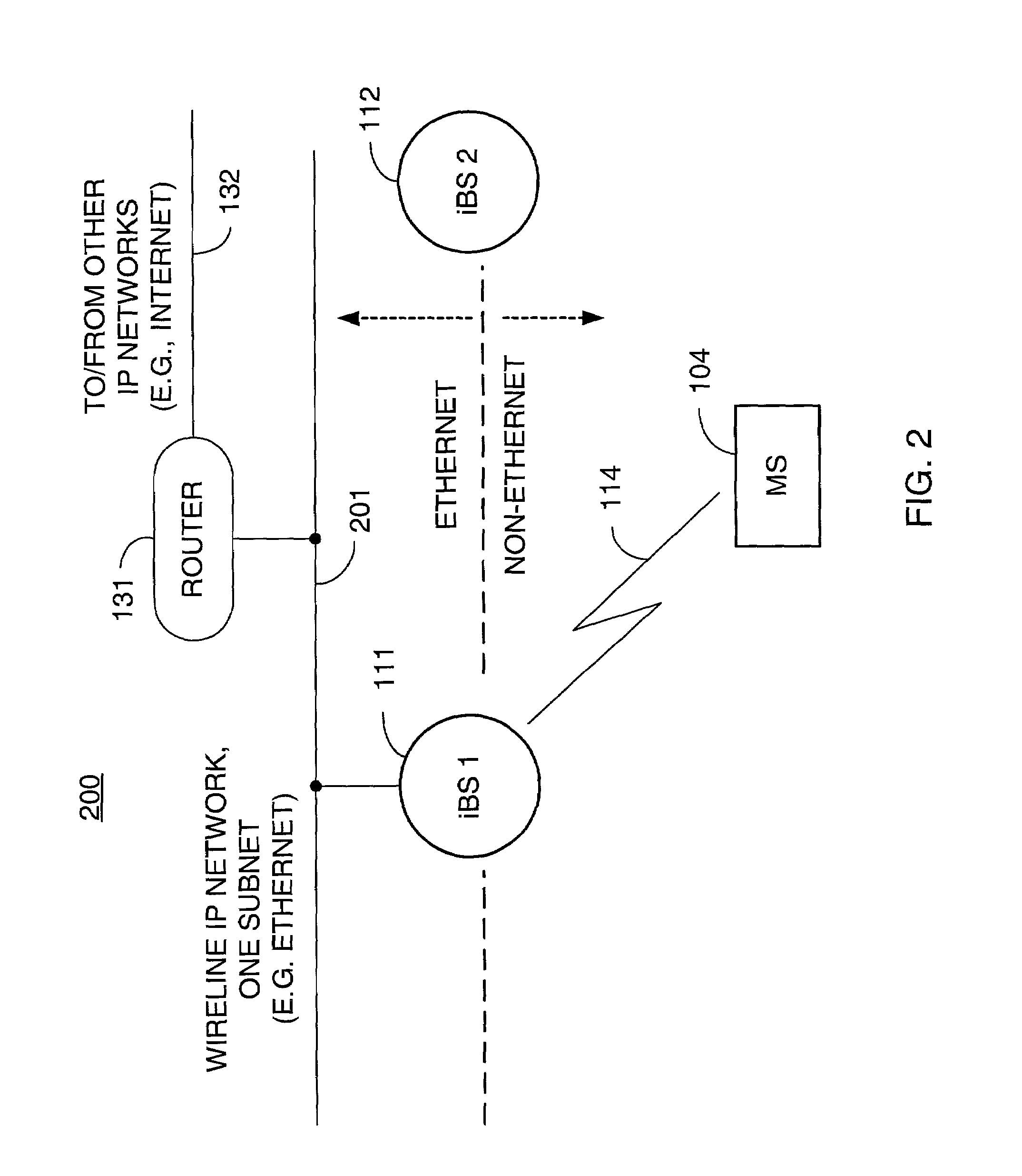
Such a design, however, has a potentially serious shortcoming.
This means that other routers will not be able to determine which base station should receive a packet destined for a host on subnet S. In other words, packets may be delivered to the wrong base station and consequently cannot reach the destined host.
Changing IP address usually takes a long time using today's methods for dynamic IP address assignment (e.g., the Dynamic Host Configuration Protocol or DHCP).
Having to change IP addresses when moving from one cell to another also makes soft handoff more difficult to implement.
Consequently, copies of the same packets from different base stations may not be correctly combined by the MS's radio system.
These methods, however, typically require complex IP-layer signaling and significant changes to the IP routers in the domain.
Furthermore, these methods have not considered how to solve the data content synchronization problem.
Accordingly, as evidenced by the foregoing discussion, achieving soft handoff among distributed iBSs introduces several new technical problems that cannot be solved readily by the mechanisms developed for today's centralized circuit-switched wireless networks.
One problem already alluded to is loss of data content synchronization.
Consequently, even though the CDMA radio system is capable of synchronizing the link and physical layer frames on the radio channel, it cannot, on its own, guarantee that the matching frames from different base stations will carry copies of the same data.
For example, IP packets can be lost on their way to the MS, creating random gaps in the packet streams received by the MS from different iBSs.
Furthermore, copies of the same data may arrive at the MS at different times due to the random delays suffered by the packets.
Random gaps and delays can lead to a loss of data content synchronization.
Another problem is how to support soft handoff, which requires a mobile station to receive identical copies of the same data from multiple base stations simultaneously.
Furthermore, copies of the same IP packet arriving from different base stations to the mobile station will not be identical because these packets will carry different destination IP addresses.
This makes it impossible for the mobile station's radio system to combine the signals from different base stations into a single copy of data.

Method used


Image

  • Distributed soft handoff among IP-based base stations
  • Distributed soft handoff among IP-based base stations
  • Distributed soft handoff among IP-based base stations

Examples


example 1

[0086]By way of specificity to summarize the procedure step-by-step, consider the arrangement of FIG. 13 wherein Packet A is sent from correspondent host 1305 attached to IP core network 1331, that is, the packet has IP destination address IPA and is sent from “outside” Subnet A. Since Packet A with destination address IPA is sent outside Subnet A, it is eventually routed to router 1322. Once router 1322 receives Packet A, it checks its Duplication Table. Packet A therefore will be duplicated with IP destination address of IPB as depicted in the third column of Table 4, and this duplicated packet is be routed to MS 104 via iBS B. Besides, Packet A is routed to MS 104 via iBS A as a standard packet.

[0087]If there are multiple nearest routers an iBS connects to, only one of them receives the packet sent from host 1305. Therefore only one nearest router will duplicate and distribute the packet.

[0088]As outlined above, each time a mobile station moves to a new Subnet, it must acquire a ...

example 2

[0089]For this example, suppose for the moment that host 1305 is connected to Subnet A, that is, Packet A is sent from “inside” Subnet A, so that both router 1322 and iBS A respond to an ARP REQUEST with the mobile station's shadow address. Therefore, Packet A eventually arrives at both iBS A and router 1322. The one arriving at router 1322 is forwarded to the IP address(es) in third column of the Table 4 stored in router 1322. Since this packet arriving at router 1322 is due to the entry in the Duplication Table rather than the normal routing table, router 1322 does not perform normal routing so the packet will not be sent to iBS A again. In this example, only one of the nearest routers maintains the shadow address in its Duplication Table, so that only one of them duplicates and distributes a packet.

2.3 Distribution of Same Data in Multiple Streams

[0090]When the nearest router sends out the duplicated IP packets, these packets have different IP addresses of the mobile station so t...


PUM


Abstract

A technique for assigning an address (“shadow address”) to a mobile station that is compatible with the layer-2 address on the wireline network which serves the mobile station. The shadow address is then used as a wireline identifier for the destination address for frames ultimately destined for the mobile station. The shadow address is stored in a watch list for serving base stations, and any base station receiving a frame with a shadow address in its watch list process the frame to forward it the to mobile station. In this way, the shadow address facilitates carrying out soft handoff and smooth handoff.

Description

CROSS-REFERENCE TO RELATED APPLICATION[0001]This application is a non-provisional application of provisional application Ser. No. 60 / 280,287 filed Mar. 30, 2001.BACKGROUND OF THE DISCLOSURE[0002]1. Field of the Invention[0003]This invention relates generally to a wireless-to-wireline and wireless-to-wireless communication system that is composed of wireless access networks interconnected via a wireline IP (Internet Protocol) network, and, more particularly, to methodologies and concomitant circuitry for effecting soft handoff in the wireless portion of the system.[0004]2. Description of the Background Art[0005]Today, many different wireless systems exist, ranging from indoor wireless LANs (Local Area Networks) to outdoor cellular systems. Generally, the numerous wireless systems are not compatible with each other, making it difficult to roam from one system to another. Although there have been attempts to unify third-generation wireless systems, incompatible systems are expected to ...

Claims


Application Information

Patent Timeline
Patent Type & Authority Patents(United States)
IPC IPC(8): H04Q7/00H04L12/28H04L12/56H04L29/12H04W36/18H04W80/00
CPCH04L29/12018H04L29/12311H04L61/2084H04W36/18H04L61/10H04W80/00H04L61/5084
Inventor AGRAWAL, PRATHIMACHEN, JYH-CHENGZHANG, TAO
Owner TELCORDIA TECHNOLOGIES INC
Learn More