Wireless base station and packet transfer apparatus for dynamically controlling data transmission rate

a dynamic control and data transmission technology, applied in data switching networks, instruments, frequency-division multiplexes, etc., can solve problems such as unrealistic, increased costs, and difficulty in determining a proper buffer size, and achieve the effect of maximization

Inactive Publication Date: 2006-02-21
HITACHI LTD
View PDF10 Cites 37 Cited by
  • Summary
  • Abstract
  • Description
  • Claims
  • Application Information

AI Technical Summary

Benefits of technology

[0011]It is another object of the invention to provide a wireless base station, a packet transfer apparatus, and a wireless communication system capable of avoiding packets from being discarded due to buffer overflow in a wireless base station when a radio transmission rate decreases, and maximally utilizing the radio transmission rate when the transmission rate increases.

Problems solved by technology

When the speed difference in the interwork between the IP network and the radio network is large, there is a situation such that a base station cannot transmit packets transferred from the IP network side to a mobile station, an overflow of the buffer occurs in the base station, and packets have to be discarded.
However, since the size of the buffer required by each base station changes with time, it is difficult to determine a proper buffer size.
When the buffer of a large capacity for avoiding the buffer overflow is provided in each of a number of base stations, the costs increase, and it becomes unrealistic.
Further, when a mobile station moves from one radio sector to another radio sector, packet transfer has to be carried out between the base stations for managing the radio sectors, and a large delay or packet dropout may occur.
As a result, packets are supplied only at a low speed even to a high-speed radio channel, so that radio resources are wasted.

Method used


Image

  • Wireless base station and packet transfer apparatus for dynamically controlling data transmission rate
  • Wireless base station and packet transfer apparatus for dynamically controlling data transmission rate
  • Wireless base station and packet transfer apparatus for dynamically controlling data transmission rate

Examples


first embodiment

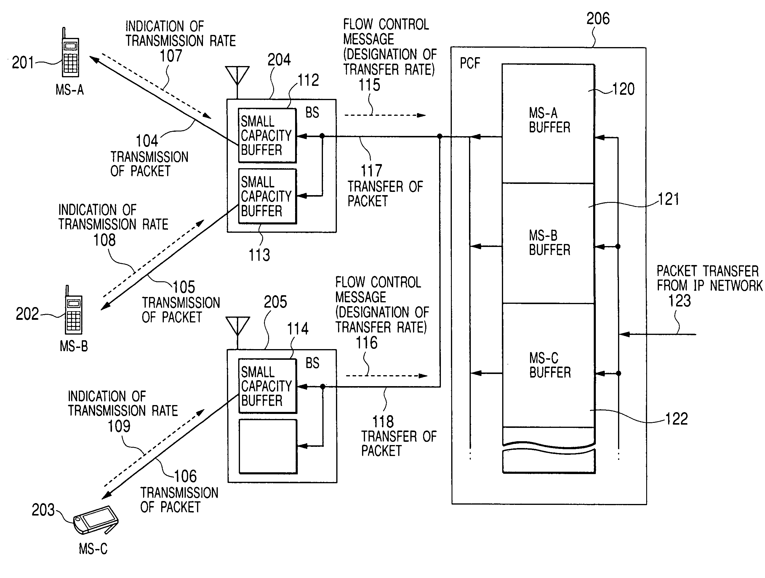
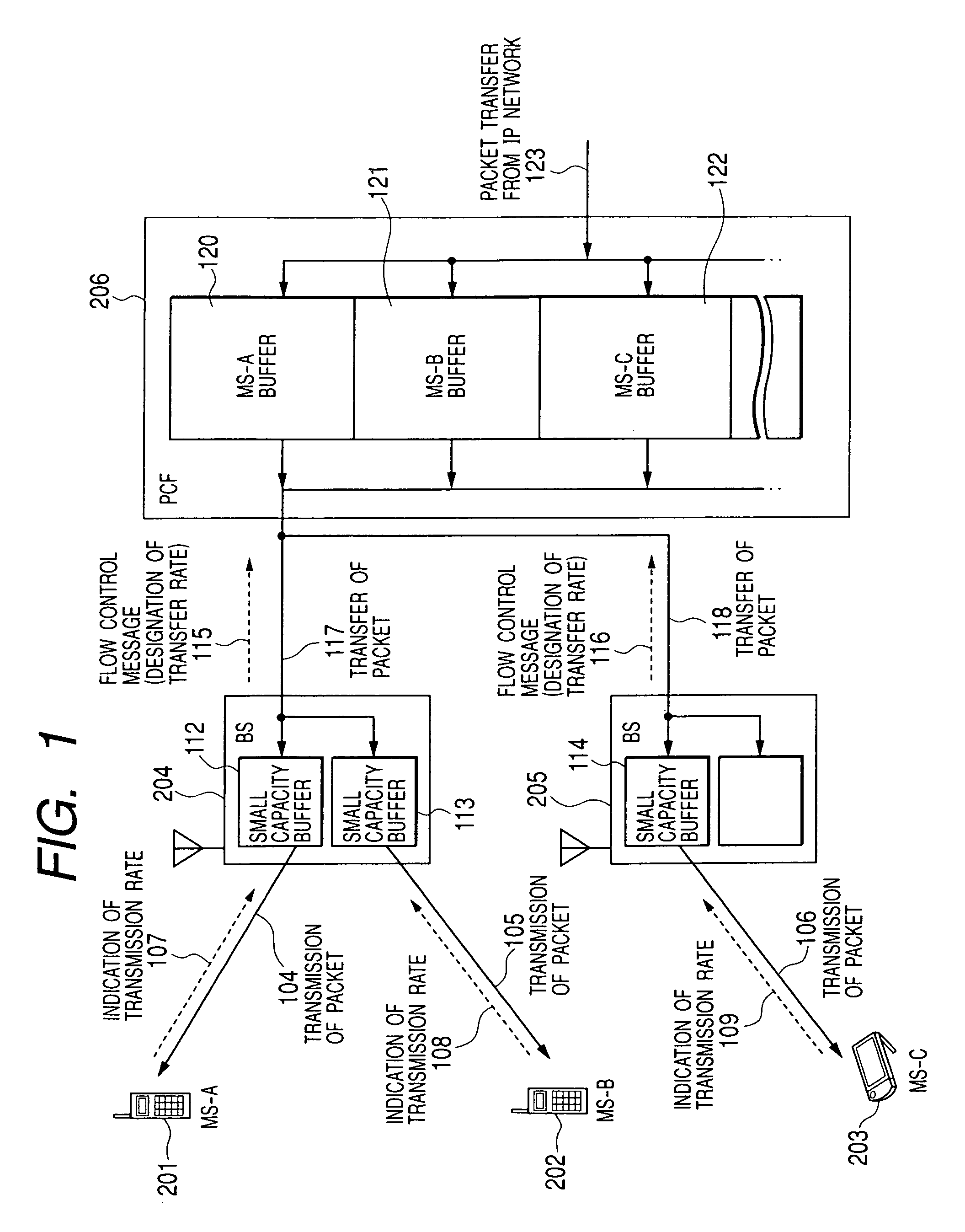
[0062]FIG. 1 shows an outline of the packet transfer control according to the invention.

[0063]A group of packet 123 sent from an IP network to a mobile station are once buffered by the PCF node 206, transferred to the base station 204 or 205 accommodating destination mobile stations, and transferred from the base station 204 to the mobile station 201 or 202 or from the base station 205 to the mobile station 203. As shown in the diagram, the base stations 204 and 205 have buffers 112 to 114 for temporarily storing received packets. Each of the buffers is of a very small capacity which is the minimum required for scheduling transmission on a radio channel or re-transmitting packets in the event that a transfer error occurs in the radio channel. The speed difference between the radio channel and the IP network is absorbed by using buffers 120 to 122 provided for the PCF node 206. By absorbing the speed difference at the PCF node, it becomes unnecessary to calculate the proper buffer si...

second embodiment

[0124]the invention will now be described.

[0125]FIG. 20 shows an outline of the second embodiment of the invention. In the second embodiment, mobile stations are grouped into rate classes according to current average values of the forward link transmission rates. In the base station 204, buffers for temporarily storing packet data to be transmitted to mobile stations are assigned to each of the groups. A packet transferred from the PCF node to the base station is temporarily stored in a buffer assigned to the group to which the destination mobile station of the packet belongs.

[0126]Each the time the received packet from the PCF node 206 is stored, the free space of the buffer in the base station decreases. When the transmission of packets to the mobile station is completed, the free space of the buffer increases. In the second embodiment, the base stations 204 and 205 notify the PCF node 206 of the free space of the buffer in each of the groups as “window size”, thereby performing t...


PUM


Abstract

In a mobile communication system in which a plurality of base stations are connected to a communication network via a packet transfer node and a transmission rate of a forward link radio channel between a base station and a mobile station dynamically changes, each of the base stations designates a packet transmission rate in accordance with the status of a radio channel of each of mobile stations under control for the packet transmission node, and the packet control node transfers packets destined for each of mobile stations to the base station at the designated transfer rate.

Description

BACKGROUND OF THE INVENTION[0001](1) Field of the Invention[0002]The present invention relates to a mobile wireless packet data communication technique and, more particularly, to a wireless base station, a packet transfer apparatus, and a wireless communication system adapted to a packet data wireless communication system in which a data transmission rate dynamically changes in a radio channel.[0003](2) Description of the Related Art[0004]In recent years, rapid growth of the Internet creates new needs for the high-speed wireless transmission technique. Awireless portable terminal performs not only speech communications but also, for example, communications of electronic mails, accesses to the Web, and increasingly uses an application via an IP network accompanying data transfer of a large amount such as distribution of music data and image data.[0005]In the wireless data communications, when the status of a radio path deteriorates and a noise level becomes higher than a reception si...

Claims


Application Information

Patent Timeline
Patent Type & Authority Patents(United States)
IPC IPC(8): H04Q7/20H04L12/66H04B7/212H04B7/24H04B7/26H04L1/00H04L12/28H04W28/00H04W28/14H04W28/22H04W72/04H04W84/12H04W92/10H04W92/12
CPCH04L1/0002H04W28/22H04W92/10H04W28/14
Inventor YOSHIDA, KIYOHIKOAOE, HIDEOMIYAZAKI, SHUICHIKOZAWA, SHUUICHIHIRAYAMA, KOJI
Owner HITACHI LTD
Why Eureka
Try Eureka