Projection system with scrolling unit

a projection system and scrolling technology, applied in the field of projection systems, can solve the problems of reducing yield, bulky optical system, complicated and expensive single-panel projection system, etc., and achieve the effect of increasing light efficiency, maximizing light utilization, and high efficiency

Inactive Publication Date: 2006-12-19
SAMSUNG ELECTRONICS CO LTD
View PDF15 Cites 5 Cited by
  • Summary
  • Abstract
  • Description
  • Claims
  • Application Information

AI Technical Summary

Benefits of technology

[0021]An apparatus consistent with the present invention provides a highly efficient projection system which increases the light efficiency by maximally utilizing the light emitted from a light source and is compact since only a single scrolling unit is used to scroll color bars.

Problems solved by technology

A 3-panel projection system provides better light efficiency than a single-panel projection system but is more complicated and expensive than the single-panel projection system.
Hence, the conventional optical system is bulky, and the manufacturing and assembly thereof is complicated, thus decreasing the yield.
Thus, the projection system adopting three motors is manufactured at a greater cost than a color wheel type projection system which utilizes a single motor.
However, controlling the synchronization is not easy.
Due to the circular motion of the scrolling prisms 114, 135, and 142, the color scrolling speed by the three scrolling prisms is irregular, consequently deteriorating the quality of the resultant image.
Furthermore, the structure of the PCS 105 is complicated.

Method used


Image

  • Projection system with scrolling unit
  • Projection system with scrolling unit
  • Projection system with scrolling unit

Examples


Embodiment Construction

[0053]An apparatus consistent with the present invention will now be described more fully with reference to the accompanying drawings, in which illustrative, non-limiting embodiments of the invention are shown. In the drawings, like reference numbers refer to like elements throughout and the sizes of elements may be exaggerated for clarity.

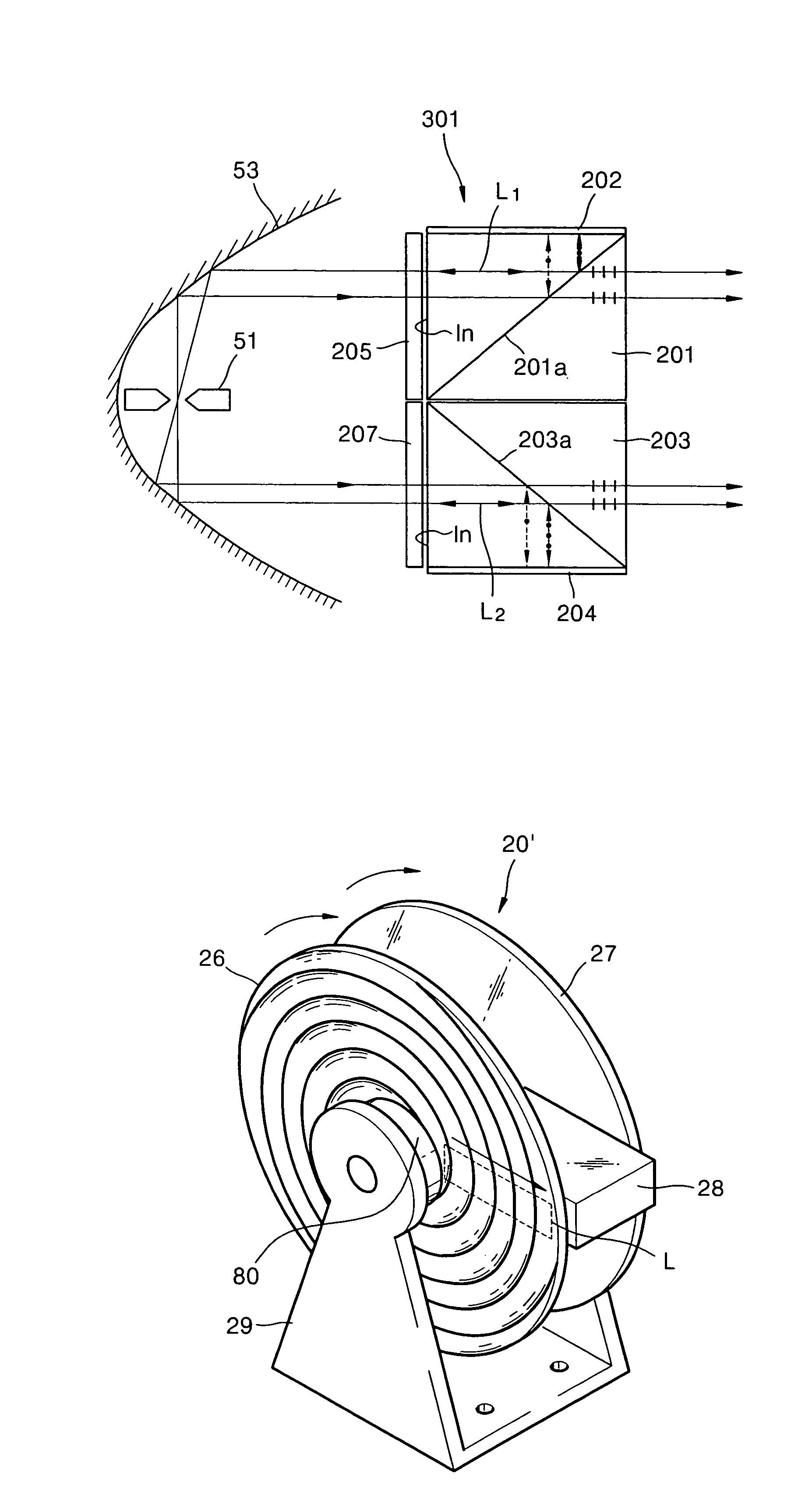
[0054]FIG. 4 is a schematic diagram of a projection system according to a first embodiment of the present invention. Referring to FIG. 4, the projection system according to the first embodiment of the present invention includes a light source 51, a polarization conversion system (PCS) 301, a reflection mirror 53, a color separator 15, a scrolling unit 20, a light valve 40, and a projection lens unit 45. The PCS 301 reflects a beam having one polarization of a beam received from the light source 51 back to the reflection mirror 53. The reflection mirror 53 reflects the received beam to the PCS 301. The color separator 15 separates light transmitted...


PUM

PropertyMeasurementUnit
coloraaaaaaaaaa
areaaaaaaaaaaa
¼ wavelengthaaaaaaaaaa

Abstract

A projection system including a light source, a polarization conversion system, a reflection mirror, a color separator, a scrolling unit, a light valve, and a projection lens unit is provided. The polarization conversion system includes an incidence plane through which light emitted from the light source enters, and transmits a beam with a first polarization from the light entering through the incidence plane and reflects a beam with a second polarization toward the incidence plane and then changes the polarization of the reflected beam. The reflection mirror reflects the light emitted from the polarization conversion system through the incidence plane back toward the incidence plane. The color separator separates an incident beam according to color. The scrolling unit scrolls the color beams. The light valve processes an incident beam according to an image signal and forms a color picture. The projection lens unit magnifies and projects the color picture onto a screen.

Description

[0001]This application claims the benefits of Korean Patent Application No. 2003-23976, filed on Apr. 16, 2003, in the Korean Intellectual Property Office, and U.S. Patent Provisional Application No. 60 / 457,569, filed on Mar. 27, 2003, in the U.S. Patent Trademark Office, the disclosures of which are incorporated herein in their entireties by reference.BACKGROUND OF THE INVENTION[0002]1. Field of the Invention[0003]An apparatus consistent with the present invention relates to a projection system and, more particularly, to a highly efficient projection system with an increased light efficiency which maximally uses light emitted from a light source and is made compact by using a single scrolling unit to scroll color bars.[0004]2. Description of the Related Art[0005]In a conventional projection system, a light valve, such as a liquid crystal display (LCD) or a Digital Micro-mirror Device (DMD), controls the on / off operation of light emitted from a light source on a pixel-by-pixel basis...

Claims


Application Information

Patent Timeline
Patent Type & Authority Patents(United States)
IPC IPC(8): G03B21/14G02F1/1335G02F1/13363H04N9/14G03B21/20H04N9/31
CPCH04N9/3117H04N9/3197G03B21/2073G03B21/208G03B21/14
Inventor KIM, SUNG-HACHO, KUN-HOKIM, DAE-SIKLEE, HEE-JOONG
Owner SAMSUNG ELECTRONICS CO LTD
Why Eureka
Try Eureka