
Variable area nozzle for gas turbine engines driven by shape memory alloy actuators

a technology of shape memory alloy and variable area nozzle, which is applied in the direction of liquid fuel engine, mechanical control device, instruments, etc., can solve the problems of engine stall, cruise performance and fuel efficiency often compromised, and the requirements for take-off and landing conditions are different, so as to improve the overall fuel efficiency of the gas turbine engine

Inactive Publication Date: 2006-02-28
RAYTHEON TECH CORP
View PDF17 Cites 51 Cited by
  • Summary
  • Abstract
  • Description
  • Claims
  • Application Information

AI Technical Summary

Benefits of technology

[0014]One major advantage of the present invention is that the SMA actuated variable area nozzle does not require complex mechanisms necessitating extensive maintenance.
[0015]Another major advantage of the present invention is that the SMA actuated variable area nozzle does not add significant weight to the engine, thereby improving the benefits associated with the overall fuel efficiency increase of the gas turbine engine.

Problems solved by technology

However, the requirements for take-off and landing conditions are different from requirements for the cruise condition.
For cruise conditions, it is desirable to have a smaller diameter fan nozzle for increasing cruise performance and for maximizing fuel efficiency, whereas, for take-off and landing conditions, smaller diameter fan nozzles may cause an engine stall.
Therefore, in many conventional engines, the cruise performance and fuel efficiency are often compromised to ensure safety of the gas turbine engine at take-off and landing.
The existing variable area nozzles are either hydraulically or pneumatically actuated and result in complex mechanisms that require extensive maintenance.
Furthermore, the existing variable area nozzle mechanisms add significant weight to the engine.
As is well known in the art, the extra weight adversely effects the overall performance of the aircraft.
The additional weight reduces aircraft range and can result in additional fuel consumption for operation of the engine.
Thus, although variable area nozzles have been introduced into some gas turbine engines, the use of existing variable area nozzles on most aircraft is not practical.

Method used


Image

  • Variable area nozzle for gas turbine engines driven by shape memory alloy actuators
  • Variable area nozzle for gas turbine engines driven by shape memory alloy actuators
  • Variable area nozzle for gas turbine engines driven by shape memory alloy actuators

Examples


Embodiment Construction

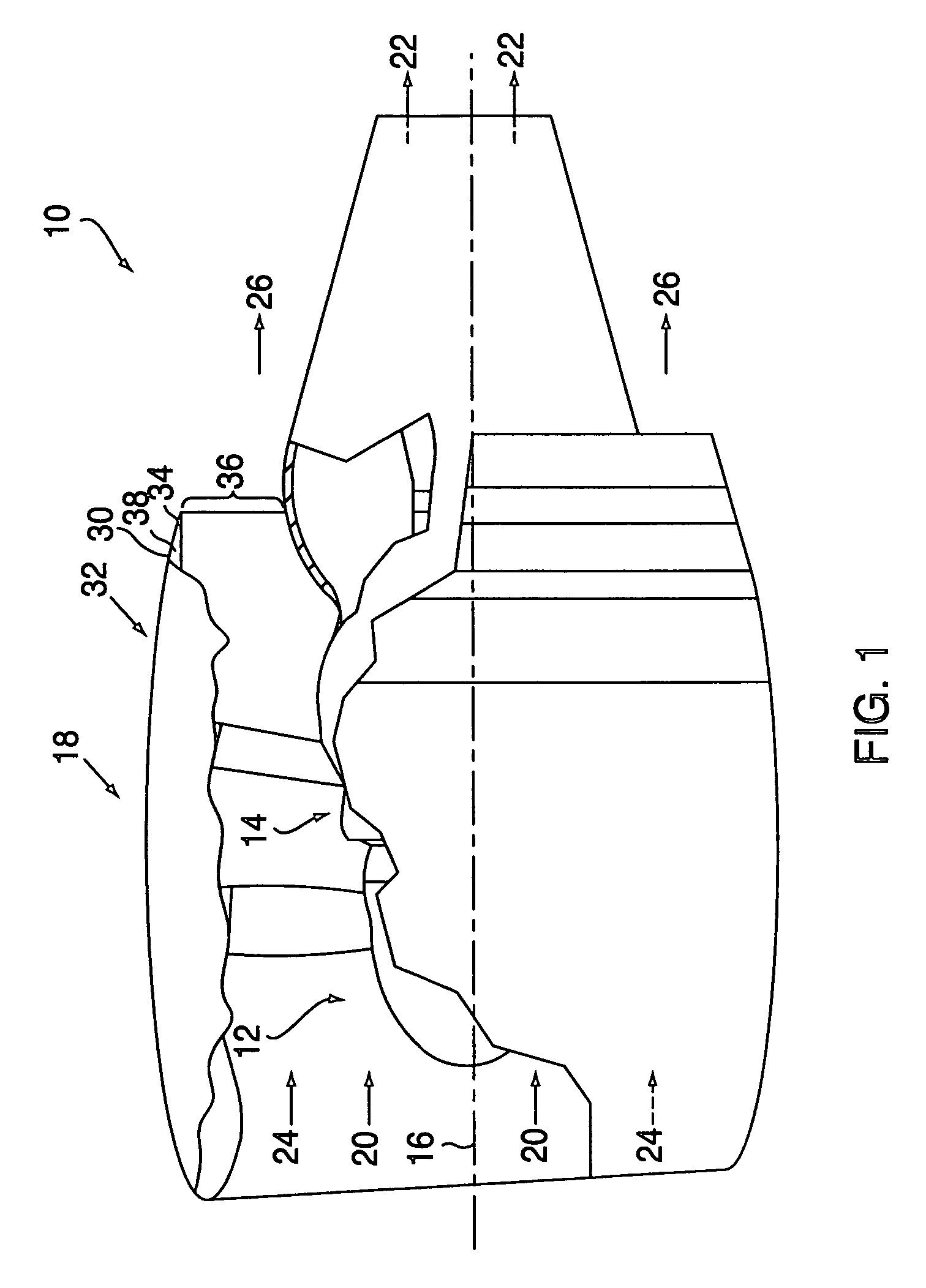
[0028]Referring to FIG. 1, a gas turbine engine 10 includes a fan section 12 and a core engine 14 disposed sequentially about a longitudinal axis 16. The core engine 14 and the fan section 12 are enclosed in a nacelle 18. An annular path of primary airflow 20 passes through the fan section 12 and the core engine 14, generating primary thrust 22. An annular path of fan flow 24, disposed radially outward of the path of the primary air flow 20, bypasses the core engine 14 and flows through the fan section 12, generating fan thrust 26.

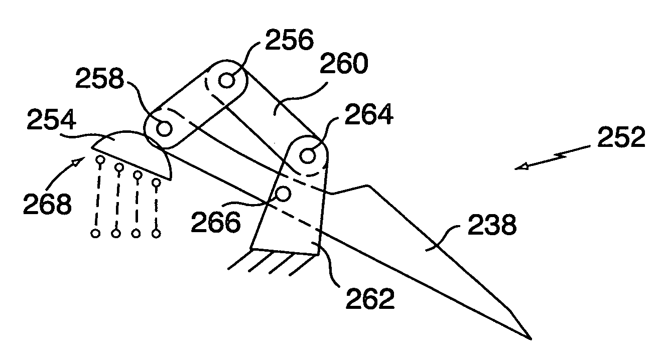
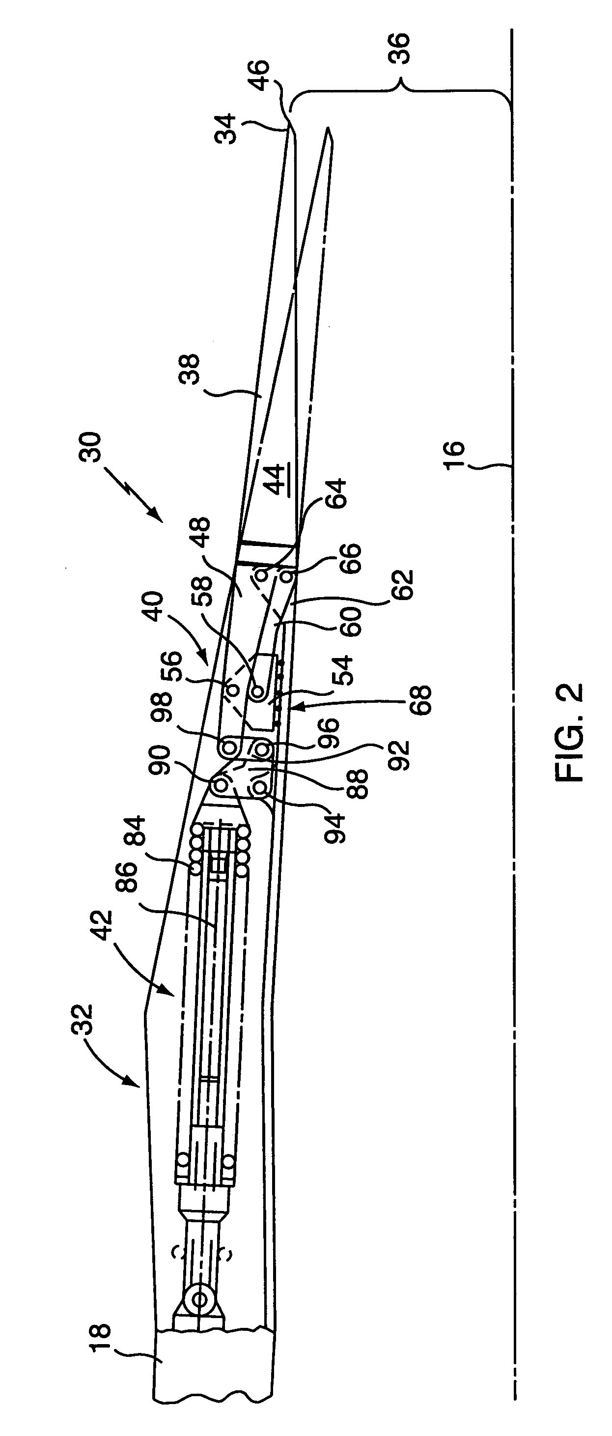
[0029]A variable area nozzle 30, shown in greater detail in FIGS. 2 and 3, is disposed in a downstream portion 32 of the nacelle 18 with a trailing edge 34 of the nacelle 18 defining a fan exit nozzle area 36. Referring to FIGS. 2 and 3, the variable area nozzle 30 includes a plurality of flaps 38, circumscribing the core engine 14, a plurality of actuating mechanisms 40, and a plurality of return mechanisms 42, with each actuating mechanism 40 and each re...


PUM


Abstract

A gas turbine engine includes a variable area nozzle having a plurality of flaps. The flaps are actuated by a plurality of actuating mechanisms driven by shape memory alloy (SMA) actuators to vary fan exist nozzle area. The SMA actuator has a deformed shape in its martensitic state and a parent shape in its austenitic state. The SMA actuator is heated to transform from martensitic state to austenitic state generating a force output to actuate the flaps. The variable area nozzle also includes a plurality of return mechanisms deforming the SMA actuator when the SMA actuator is in its martensitic state.

Description

CROSS-REFERENCE TO RELATED APPLICATION[0001]This application is a divisional application of Ser. No. 09 / 824,419, filed Apr. 2, 2001 now U.S. Pat. No. 6,735,963 and also of application Ser. No. 09 / 517,937 filed Mar. 3, 2000 now U.S. Pat. No. 6,318,070.[0002]This application relates to an application entitled “Shape Memory Alloy Bundles and Actuators”, having an Attorney Docket No. EH-10350-3 / 3309P-110, filed on the same date herewith and assigned to a common assignee.BACKGROUND OF THE INVENTION[0003]1. Technical Field[0004]This invention relates to gas turbine engines and, more particularly, to variable area nozzles driven by shape memory alloy actuators therefor.[0005]2. Background Art[0006]Conventional gas turbine engines include a fan section and a core engine with the fan section having a larger outer diameter than that of the core engine. The fan section and the core engine are disposed sequentially about a longitudinal axis and are enclosed in a nacelle. An annular path of prim...

Claims


Application Information

Patent Timeline
IPC IPC(8): G05G1/00F02K1/06F02K1/12F02K3/06F02K3/075F03G7/06F04D29/56
CPCF02K1/1207F03G7/065Y10T74/20F05D2300/505Y02T50/671Y02T50/60
Inventor REY, NANCY M.MILLER, ROBIN M.TILLMAN, THOMAS G.RUKUS, ROBERT M.KETTLE, JOHN L.
Owner RAYTHEON TECH CORP
Learn More