Continuously variable transmission for bicycles

a technology of continuously variable transmission and bicycle, which is applied in the direction of friction roller based transmission, cycle equipment, gearing, etc., can solve the problems of reduced freedom of the layout of the speed increasing mechanism with respect to the bicycle frame, increased cost of continuously variable transmission, poor etc., to reduce the size of the speed increasing mechanism, and improve the maneuverability of the bicycle

Inactive Publication Date: 2006-02-28
HONDA MOTOR CO LTD
View PDF5 Cites 33 Cited by
  • Summary
  • Abstract
  • Description
  • Claims
  • Application Information

AI Technical Summary

Benefits of technology

[0007]The present invention has been made in view of the above problems. One object of the present invention is to provide a continuously variable transmission for bicycles which provides better bicycle maneuverability, and suffers almost no danger of contacting the ground, while reducing cost. Another object of the present invention is to prevent contact of the continuously variable transmission and the drive rotor with the ground. A third object of the present invention defined is to reduce the size of the speed increasing mechanism, thus increasing the freedom of the layout thereof with respect to a bicycle frame.
[0008]According to a first aspect of the present invention, there is provided a continuously variable transmission for bicycles which includes a transmission mechanism having a plurality of link units, each having a plurality of transmission links, for converting rotary motion of an input shaft rotated by a pedal-operated crankshaft into swinging motion, a one-way clutch coupled to each of the link units for converting the swinging motion of the link units into rotary motion of an output shaft, and a transmission control mechanism for moving an end of a transmission control link having an opposite end pivotally coupled to each of the link units thereby to continuously vary the rotational speed of the output shaft.

Problems solved by technology

According to the above reference, since the transmission which is a heavy object is positioned near the axle of the rear wheel which is spaced from the center of gravity of the bicycle body, the maneuverability of the bicycle is poor.
Furthermore, since a portion of the transmission is positioned below the axle, it may possibly contact the ground when the bicycle travels on rough terrain.
Further, a difficulty arises in that the layout of the speed increasing mechanism with respect to the bicycle frame suffers reduced freedom.
If the range of angular movement of the crank rod is changed to change the range of speed change ratios depending on the type of the bicycle or due to specification changes, then the crankshaft itself needs to be replaced, resulting in an increase in the cost of the continuously variable transmission.

Method used


Image

  • Continuously variable transmission for bicycles
  • Continuously variable transmission for bicycles
  • Continuously variable transmission for bicycles

Examples


Embodiment Construction

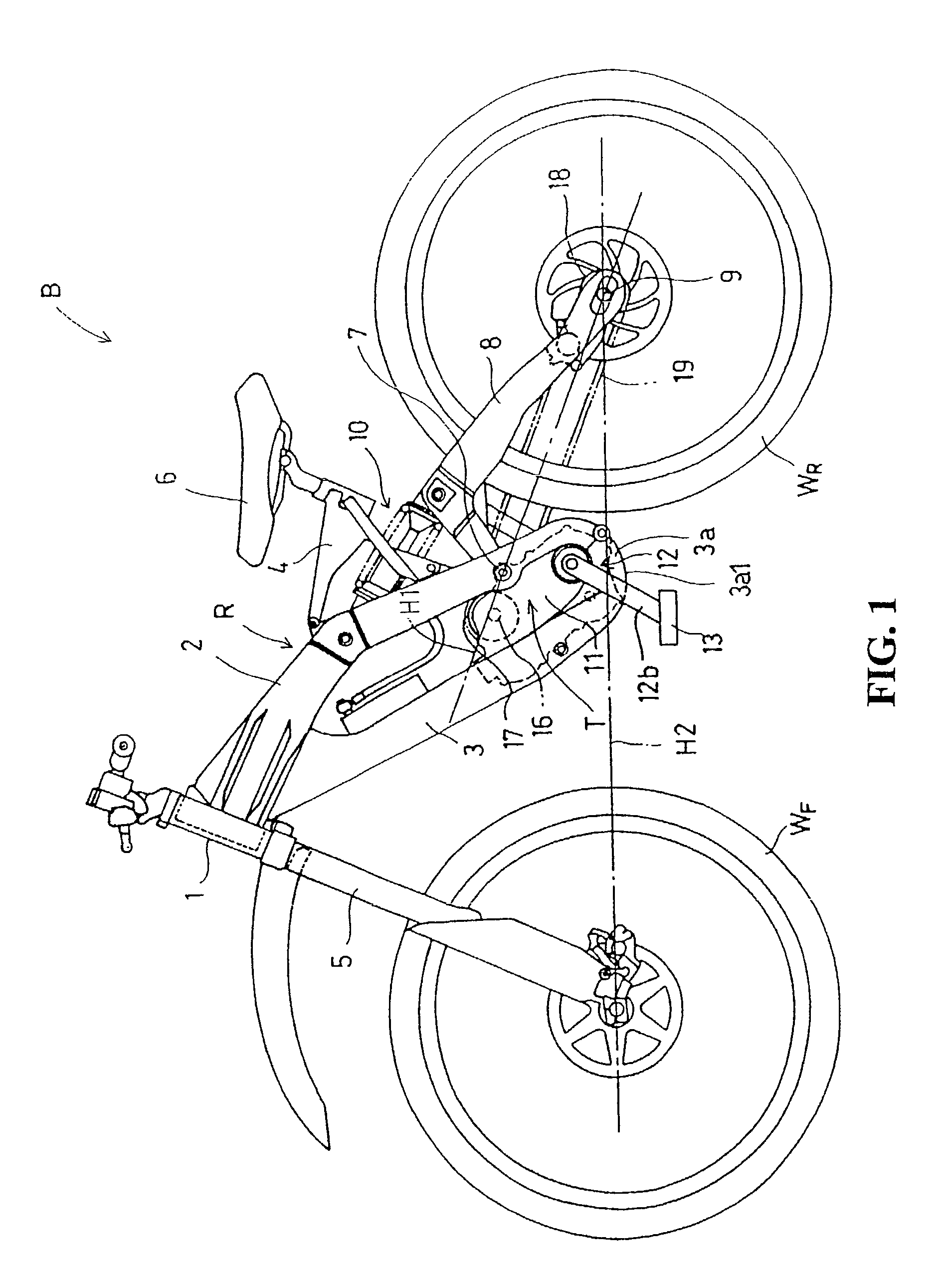
[0036]Referring to FIG. 1 which is a left side-elevational view of a bicycle that is equipped with a continuously variable transmission according to the present invention, a bicycle B is a downhill bicycle and is used in competitions in which it runs down an unpaved course with high-speed corners and jump sections, such as along a forest trail with ups and downs, to compete for time.

[0037]The bicycle B has a bicycle frame R comprising a head pipe 1 which steerably supports on its lower end a front fork 5 having a pair of left and right legs on which a front wheel WF is supported by an axle, a pair of left and right main frames 2 extending rearwardly and obliquely downwardly from the head pipe 1, a down tube 3 extending rearwardly and obliquely downwardly from front ends of the main frames 2 below the main frames 2, and a saddle frame 4 extending from a central portion of the main frames 2 and supporting a saddle 6.

[0038]A pair of left and right swing arms 8 have front ends angularly...


PUM


Abstract

A continuously variable transmission for bicycles having a transmission mechanism including a plurality of link units for converting rotary motion of an input shaft rotated by a pedal-operated crankshaft into swinging motion, and a one-way clutch for converting the swinging motion into rotary motion of an output shaft. The link units have drive links pivotally mounted on an eccentric ring which rotates in unison with the input shaft. The continuously variable transmission is disposed between a front wheel and a rear wheel of a bicycle in the longitudinal direction thereof and disposed either upwardly of a hypothetical plane which contains the axes of rotation of the front wheel and the rear wheel or upwardly of a position below and near the hypothetical plane. The transmission so configured provides better bicycle maneuverability, lower cost, while suffering almost no danger of contacting the ground.

Description

CROSS-REFERENCE TO RELATED APPLICATION[0001]The present application claims priority under 35 U.S.C. §119 to Japanese Patent Application No. 2002-160804, filed May 31, 2002, the entire contents of which are hereby incorporated by reference.BACKGROUND OF THE INVENTION[0002]1. Field of the Invention[0003]The present invention relates to a continuously variable transmission for bicycles, and more particularly to a continuously variable transmission including a plurality of link units for converting rotary motion of an input shaft into swinging motion, a one-way clutch for converting the swinging motion into rotary motion of an output shaft, and a transmission control mechanism for continuously varying the rotational speed of the output shaft.[0004]2. Description of Background Art[0005]There has heretofore been known a continuously variable transmission for bicycles of the type described above, as disclosed in Japanese patent laid-open No. Sho 54-120146. This continuously variable transm...

Claims


Application Information

Patent Timeline
Patent Type & Authority Patents(United States)
IPC IPC(8): B62M9/00B62M9/04B62M9/08F16H1/20F16H21/14F16H29/14
CPCB62M9/04B62M9/08Y10T74/1513Y10T74/18376Y10T74/151
Inventor MATSUMOTO, SHINYAINOUE, NAOKITSUKADA, YOSHIAKI
Owner HONDA MOTOR CO LTD
Why Eureka
Try Eureka