Stick-like paint container

a cosmetic container and stick-type technology, applied in the direction of propelling pencils, packaging goods types, packaged foodstuffs, etc., can solve the problems of inconvenient use of the container, inability to easily perform filling, disassembly, assembly, etc., and achieve the effect of improving the shape of the inner container guiding groov

Inactive Publication Date: 2006-02-28
KOBAYASHI KOSE CO LTD
View PDF8 Cites 5 Cited by
  • Summary
  • Abstract
  • Description
  • Claims
  • Application Information

AI Technical Summary

Benefits of technology

[0011]The present inventors have conducted extensive studies to achieve the above objects. As a result, the inventors have found that refilling and replacement can be easily performed only for the inner container filled with a stick-type cosmetic, while the inner container can be prevented from dropping out during normal use, by improving the shape of the inner container guiding groove provided in the sleeve.
[0012]The inventors have also found that it is not necessary to provide the junction for securing the inner container in order to prevent dropout used in a conventional stick-type cosmetic container, when a plurality of pawls are provided in the rotational cylinder and engaged with a rib provided on the outer surface approximately at the center of the sleeve. These findings have led to the completion of the present invention.

Problems solved by technology

However, the container is highly inconvenient for use in terms of replacement of the inner container 5, separate disposal of the metal and resin, and the like.
However, the disassembly is practically impossible because the outer cylinder 12 is secured to the junction 13.
However, due to the above-mentioned reasons, a stick-type cosmetic container for which filling, disassembly, assembly, and separate disposal can be easily performed has not yet been provided.

Method used


Image

  • Stick-like paint container
  • Stick-like paint container
  • Stick-like paint container

Examples


Embodiment Construction

[0025]The present invention will be described in more detail with reference to the drawings showing one embodiment of the present invention. However, the present invention is not limited to this embodiment.

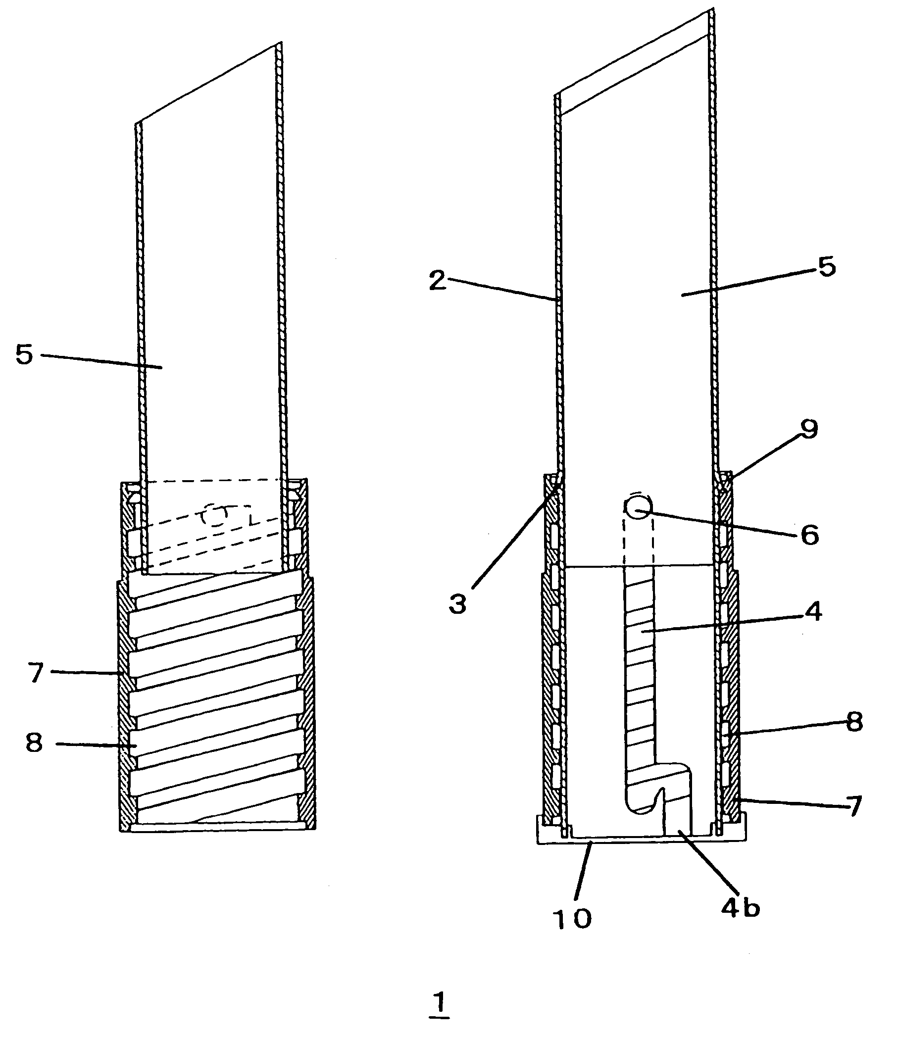
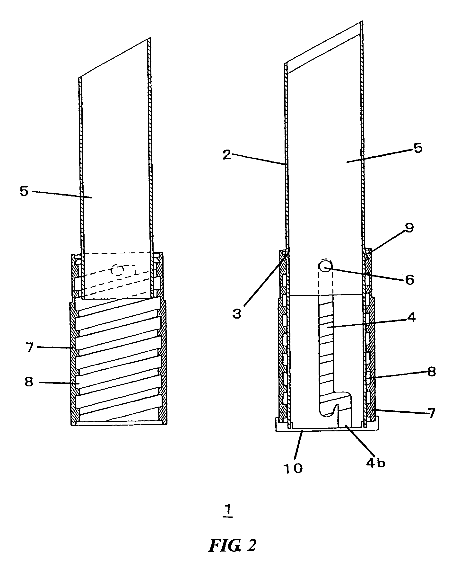
[0026]FIG. 2 is a drawing showing a configuration of an internal structure used in the stick-type cosmetic container of the present invention. (An exterior container is not shown.) In FIG. 2, the view on the right is a cross-sectional view substantially showing only the inner container, and the view on the left is a cross-sectional view showing a state in which a sleeve 2 is removed. (A stick-type cosmetic is not shown.) In FIG. 2, 1 indicates an internal structure of the stick-type cosmetic container, 2 indicates a sleeve, 3 indicates a cyclic rib, 4 indicates a inner container guiding groove, 4b indicates a secondary groove, 5 indicates an inner container, 6 indicates a small projection, 7 indicates a rotational cylinder, 8 indicates a screw, 9 indicates a pawl, and 10 indicates...


PUM


Abstract

A stick-type cosmetic container, comprising an internal structure having a rotational cylinder, a sleeve, and an inner container for filling a stick-type cosmetic therein and allowing the stick-type cosmetic filled in the inner container to be projected and retracted by guiding a small projection provided on the inner container by an inner container guiding groove provided in the sleeve and vertically moving the small projection by a screw threaded in the inner surface of the rotational cylinder, characterized in that the inner container guiding groove provided in the sleeve inside the internal structure is formed of a primary linear groove having a closed bottom end and a secondary groove branched on the way of the primary groove, formed in an approximately inverse J-shape and having an open bottom end, whereby, in normal use, the inner container is not fallen down and, when the stick-type cosmetic is used up, the inner container can be easily disassembled and a member can be easily replaced by using a simple jig, and the stick-type cosmetic container can be used for those cosmetics such as lipstick, lip cream, concealer, skin whitening stick, and sun-burn stick.

Description

TECHNICAL FIELD[0001]The present invention relates to a container for a stick-type cosmetic. More particularly, the present invention relates to a container for a stick-type cosmetic which has a small number of components and can be easily disassembled and assembled. The stick-type cosmetic container is used by placing an internal structure having a function of allowing a stick-type cosmetic filled in an inner container to be projected and retracted in an outer cylinder or exterior container.BACKGROUND ART[0002]A stick-type cosmetic container in which a stick-type cosmetic filled therein is projected and retracted by rotating an outer cylinder is widely used as a container for lipsticks and other cosmetics such as lip creams and concealers because of its ease of use.[0003]As shown in FIG. 1, a conventional stick-type cosmetic container comprises a rotational cylinder 7, sleeve 2, inner container 5 filled with a stick-type cosmetic, outer cylinder 12, and junction 13, for example. In...

Claims


Application Information

Patent Timeline
Patent Type & Authority Patents(United States)
IPC IPC(8): B43K21/08A45D40/06A45D40/12A45D40/16
CPCA45D40/06A45D40/16A45D40/12
Inventor KURIHARA, MITSURUNAKAMURA, MITSUNOBUIWASAKI, KAZUTSUGUIMABEPPU, SHIGETOARAI, KEI
Owner KOBAYASHI KOSE CO LTD
Why Eureka
Try Eureka