Pulley unit

a technology of slits and pulleys, applied in mechanical actuated clutches, hoisting equipment, gearing, etc., can solve the problems of low efficiency of forming slits, need for treatment afterward, and danger of inner ring cracking, so as to simplify the fabrication procedure

Inactive Publication Date: 2006-02-28
KOYO SEIKO CO LTD
View PDF23 Cites 12 Cited by
  • Summary
  • Abstract
  • Description
  • Claims
  • Application Information

AI Technical Summary

Benefits of technology

[0009]A primary object of the present invention is to provide a pulley unit, comprising the structure of the axial positioning of the cage of the one-way clutch, which has no structurally fragile portion while achieving a simplified fabrication procedure.
[0012]Due to the structure according to the present invention, the movement of the cage in the pulley unit is constrained in an axial direction, without using the recessing and projecting portions for constraining such a movement, which are disposed in the cage and the inner ring of the pulley unit in the prior art. Therefore, the structure of the pulley unit can be simplified and structurally fragile portions can be eliminated. Moreover, the fabrication processes to form such recessing and projecting portions can be omitted, thus the fabrication cost can be reduced.

Problems solved by technology

Thus there is danger of cracking of the inner ring 85 starting from the stress concentrated point.
Other problems are the low efficiency of the working to form the slits 91, 91, and the necessity of the treatment afterward for removing burr.
Therefore the fabrication cost is expensive.

Method used


Image

  • Pulley unit
  • Pulley unit
  • Pulley unit

Examples


Embodiment Construction

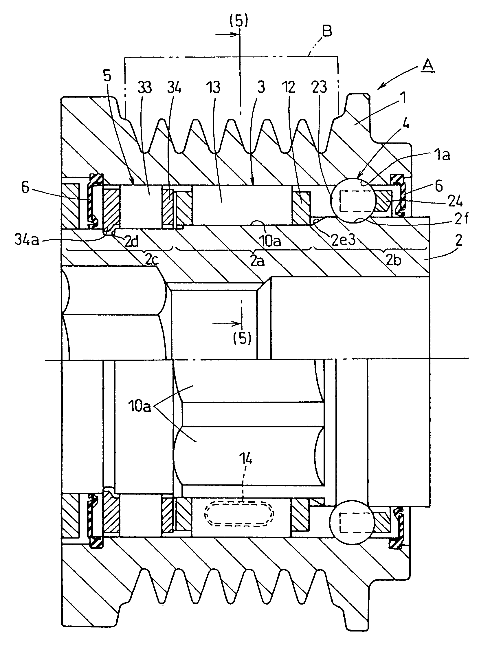
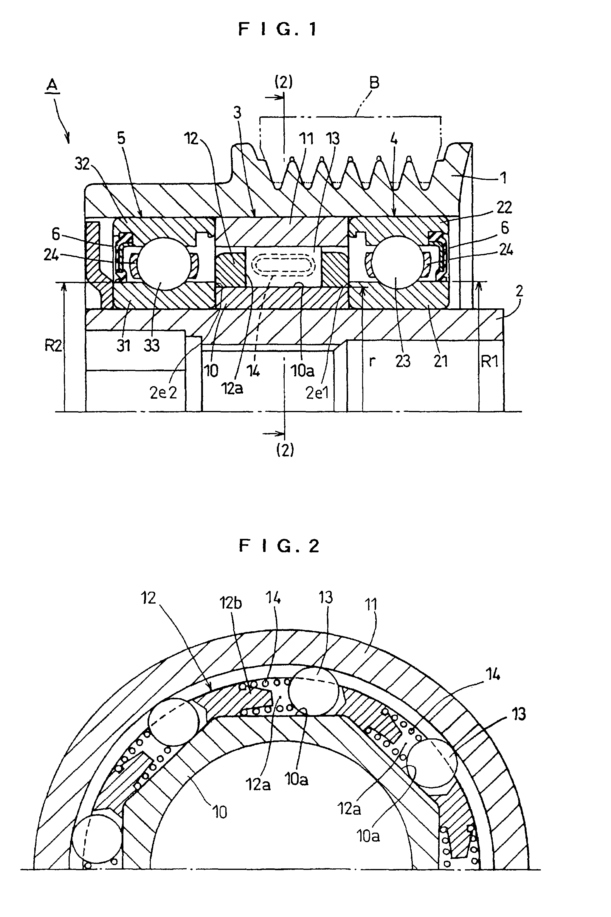
[0025]A preferred embodiment of the present invention is explained bellow, referring to FIGS. 1 to 3.

[0026]The pulley unit A comprises a pulley 1, a hollow shaft 2, a one-way clutch 3 and two rolling bearings 4 and 5.

[0027]The pulley 1, which is an example of the external ring, has an undulated groove on the peripheral surface, for putting a V ribbed belt B. The pulley 1 is rotatably driven by the V ribbed belt B combined with a crank shaft of an engine of a vehicle, for example.

[0028]The hollow shaft 2, which is an example of the inner shaft, is inserted into the inner side of the pulley 1 and is fixed to an input shaft of an auxiliary device of a vehicle engine (not shown), e.g., rotor of an alternator.

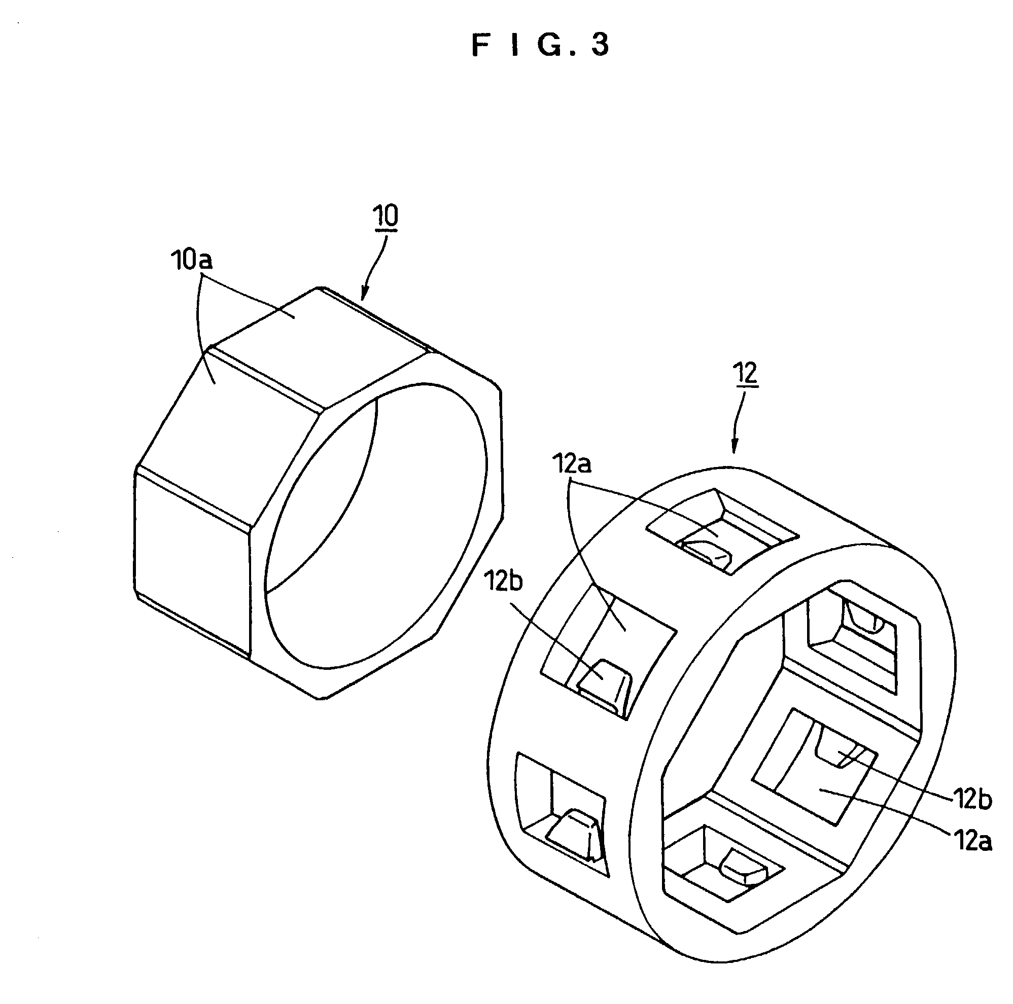
[0029]The one-way clutch 3 comprises an inner ring 10, an outer ring 11, a synthetic resin ring cage 12, a plurality of rollers 13 and an elliptic coil spring 14 as a resilient member. The owe-way clutch 3 is disposed at the center of the opposed annular space between the pulley 1 a...


PUM


Abstract

A pulley unit improved in axial positioning of a cage of a one-way clutch is provided. An outer radius of an orbital portion of inner rings of two rolling bearings disposed at both axial sides of the cage are designed to be larger than an inner radius of the cage, so that axial movement of the cage is constrained. Due to this structure, projecting and recessing portions disposed on the cage of the one-way clutch and on an inner ring become unnecessary and can be eliminated.

Description

BACKGROUND OF THE INVENTION[0001]1. Field of the Invention[0002]The present invention relates to a pulley unit to be mounted in an auxiliary device, which is a device driven by a belt combined with a crank shaft of an engine of a vehicle, for example. Examples of such an auxiliary device are a compressor for an air conditioner, a water pump, an alternator, and a cooling fan of a vehicle, for example.[0003]2. Description of the Related Art[0004]An example of such a pulley unit in the prior art is shown in FIGS. 8 and 9. In those figures, reference numerals 81, 82, 83 and 84 denote, respectively, a pulley, a shaft, a one-way clutch and a rolling bearing. The one-way clutch 83 has an inner ring 85, an outer ring 86, a plurality of rollers 87, cage 88 and a coil spring 89.[0005]When the cage 88 in such a one-way clutch 83 jolts in the angular and / or axial direction with respect to the inner ring 85, the functions of the locking in and the releasing free of the one-way clutch 83 tend to ...

Claims


Application Information

Patent Timeline
Patent Type & Authority Patents(United States)
IPC IPC(8): F16H55/36F16D41/067
CPCF16H55/36F16D41/067F16D2041/0605F16C19/49F16C41/001F16D2041/0608
Inventor FUJIWARA, HIDEKI
Owner KOYO SEIKO CO LTD
Why Eureka
Try Eureka