Optical object identification apparatus, and printing apparatus and object classification apparatus using same

a technology of object identification and printing apparatus, which is applied in the direction of electrographic process, instruments, transportation and packaging, etc., can solve the problems of conventional methods for detecting the type of recording media, deformation of recording media, and failure to detect failure due to the deterioration of contact sections

Inactive Publication Date: 2006-02-28
SHARP KK
View PDF6 Cites 18 Cited by
  • Summary
  • Abstract
  • Description
  • Claims
  • Application Information

AI Technical Summary

Benefits of technology

[0011]Accordingly, an object of the present invention is to provide an optical object identification apparatus that allows easy identification of the various types of objects with use of reflected rays of light from target objects, and to provide a printing apparatus and an object classification apparatus using the same.

Problems solved by technology

However, the above-mentioned conventional methods for detecting the type of recording media suffer a following problem.
That is, in the case of the mechanical detection method and the thermal detection method, a contact and a heating element should be brought into contact with a recording medium, which may disturb the movement of the recording medium during conveyance, and may also cause the deformation of the recording medium.
Moreover, detection failure due to the deterioration of a contact section caused by wear may occur.
Further, in the case of the aforementioned optical detection methods, the type of a recording medium is detected by the difference in the amount of reflected light from the recording medium, and therefore detection may not be possible if the difference in the amount of reflected light is small, causing considerable restraint of detectable types of recording media.
Furthermore, attention needs to be paid to the adjustment of placement angles of the light emitting device and the light receiving device, which makes assemblage of the apparatus complicated.
Furthermore, in the case of the method in which an image sensor such as CCD and C-MOS devices is used in a light receiving section, image processing becomes complicated, and pursuing higher identification accuracy increases the number of elements to be identified, thereby making the processing more complicated as well as making the light receiving device expensive.
In the case of the method in which a detection liquid is infiltrated into the recording medium at a portion to measure reflected light from that portion of the infiltrated medium, the recording medium is possibly given pigmentary change and fouling.
In addition, this method requires a means for infiltrating the detection liquid, which causes growing in size of the apparatus, and measuring of the infrared absorption spectrum complicates the configuration and signal processing of the light receiving portion.

Method used


Image

  • Optical object identification apparatus, and printing apparatus and object classification apparatus using same
  • Optical object identification apparatus, and printing apparatus and object classification apparatus using same
  • Optical object identification apparatus, and printing apparatus and object classification apparatus using same

Examples


first embodiment

[0073](First Embodiment)

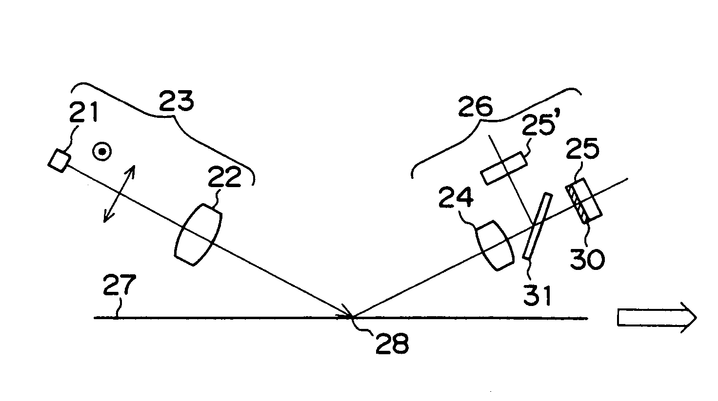
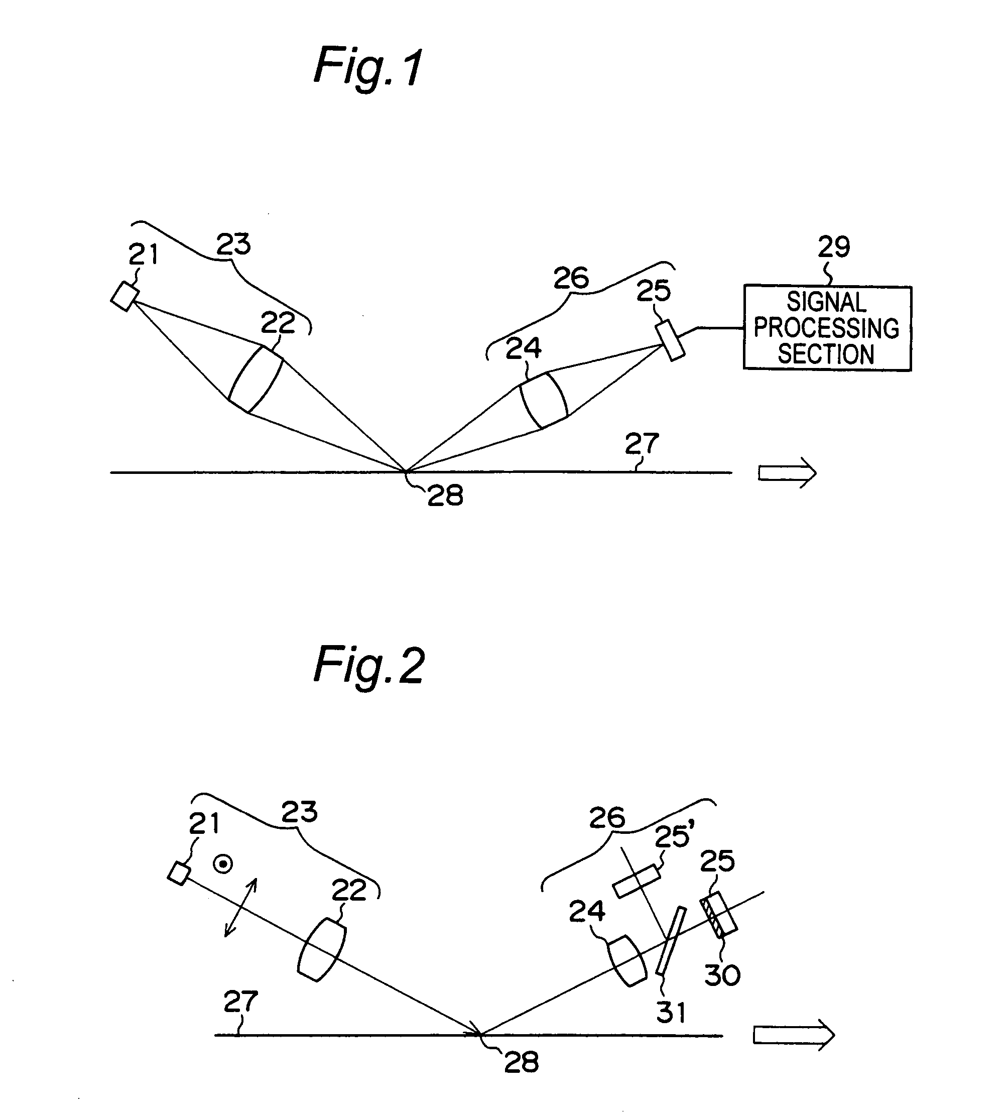
[0074]FIG. 1 is a schematic diagram showing an optical system in an optical object identification apparatus of the present embodiment. The optical object identification apparatus has at least one light emitting-side optical system 23 including a light emitting device (preferably a semiconductor laser) 21 and an objective lens 22, and at least one light receiving-side optical system 26 including a light receiving lens 24 and a light receiving device 25. By irradiating light emitted from the light emitting-side optical system 23 to a target object 27, a light spot 28 having a predetermined spot diameter (not more than 50 μm) is formed on the target object 27 moving in an arrow direction, so that reflected light from the light spot 28 enters the light receiving-side optical system 26.

[0075]Hereinbelow, detailed description will be given of the light emitting-side optical system 23 and the light receiving-side optical system 26. As shown in FIG. 2, in the light e...

second embodiment

[0090](Second Embodiment)

[0091]FIG. 10 is a schematic diagram showing optical systems in an optical object identification apparatus different from that in FIG. 1. The optical object identification apparatus in the present embodiment has a light emitting-side optical system 53 including a light emitting device (preferably a semiconductor laser) 51 and an objective and light receiving lens 52. By irradiating light emitted from the light emitting-side optical system 53 to a target object 54, a light spot 55 having a specified spot diameter (not more than 50 μm) is formed on the target object 54 moving in an arrow direction, and after reflected light from the light spot 55 is condensed by the objective and light receiving lens 52, the light is brought incident to the light receiving device 57 with its optical axis bent 90 degrees by a beam splitter 56. More specifically, the light receiving-side optical system is composed of the objective and light receiving lens 52, the beam splitter 5...

third embodiment

[0097](Third Embodiment)

[0098]FIG. 11 is a schematic diagram showing optical systems in an optical object identification apparatus of the present embodiment. The optical object identification apparatus in the present embodiment has one light emitting-side optical system 63 including a light emitting device (preferably a semiconductor laser) 61 and an objective lens 62, and two light receiving-side optical systems composed of a first light receiving-side optical system 66 including a light receiving lens 64 and a light receiving device 65, and a second light receiving-side optical system 69 including a light receiving lens 67 and a light receiving device 68. In this case, these two light receiving-side optical systems 66, 69 are disposed such that an angle α between an optical axis of one of these two light receiving-side optical systems 66, 69 (the first light receiving-side optical system 66 in the case of FIG. 11) and a target object 70 is equal to an angle α between an optical ax...


PUM

PropertyMeasurementUnit
diameteraaaaaaaaaa
length of timeaaaaaaaaaa
frequencyaaaaaaaaaa

Abstract

An optical object identification apparatus has a light emitting-side optical system (23), a light receiving-side optical system (26), and a signal processing section (29). The light emitting-side optical system (23) irradiates light from a light emitting device (21) via an objective lens (22) to a moving target object (27) such as printing paper sheets. The light receiving-side optical system (26) receives reflected light from the target object by means of the light receiving device (25) via an objective lens (24), and outputs an output signal with a waveform corresponding to the surface projections and depressions of the target object (27). The signal processing section (29) executes signal processing on the output signal by at least one signal processing method to identify the target object.

Description

[0001]This application claims priority of JP Application No. 2002-350900 filed 3 Dec. 2002, the entire contents of which is incorporated herein by reference.BACKGROUND OF THE INVENTION[0002]The present invention relates to an optical object identification apparatus for detecting the type of objects without contact, and also relates to a printing apparatus and an object classification apparatus using the same.[0003]Copying apparatuses and printing apparatuses that conduct recording processing while conveying recording media are being developed to achieve high function, high-speed processing and high resolution, and the recording media used thereby are of varied types including plain paper, glossy paper and OHP (Overhead Projector) sheets. When images are printed on such widely varying recording media by means of a printer (especially an ink jet printer) that is an image recording apparatus, it is necessary, for forming high-quality images, to execute recording control corresponding t...

Claims


Application Information

Patent Timeline
Patent Type & Authority Patents(United States)
IPC IPC(8): G01N21/86B41J2/01B41J11/00B65H7/14G01B11/30G01N21/21G01N21/47G01V8/00G03G15/08
CPCB41J11/009B41J11/0095G01N21/86G01N21/55G01B11/303
Inventor YAMAGUCHI, AKIFUMISUGIYAMA, HISAKAZU
Owner SHARP KK
Why Eureka
Try Eureka