

Method of and apparatus for detecting sensor loss in a generator control system
a sensor loss and control system technology, applied in the direction of electrical equipment, control systems, electric generator control, etc., can solve the problems of requiring immediate shut down of the generator of the sensor, the difficulty of rapidly discriminating between voltage sensor failure and output voltage collapse,
- Summary
- Abstract
- Description
- Claims
- Application Information
AI Technical Summary
Benefits of technology
Problems solved by technology
Method used
Image

Examples
Embodiment Construction
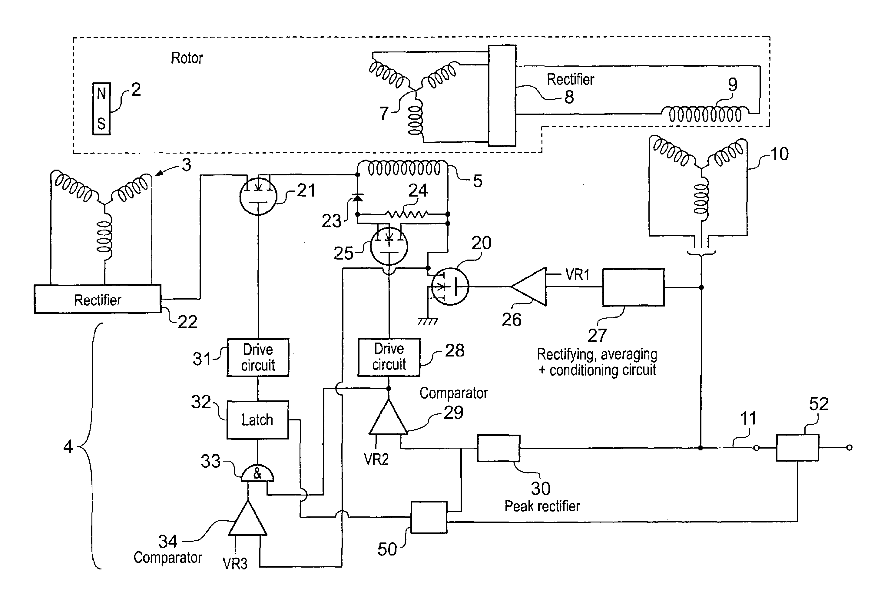
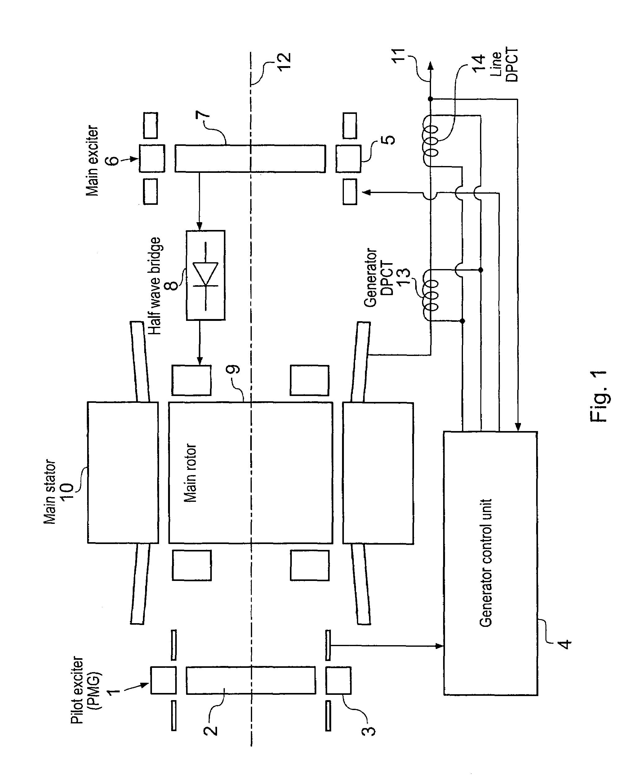
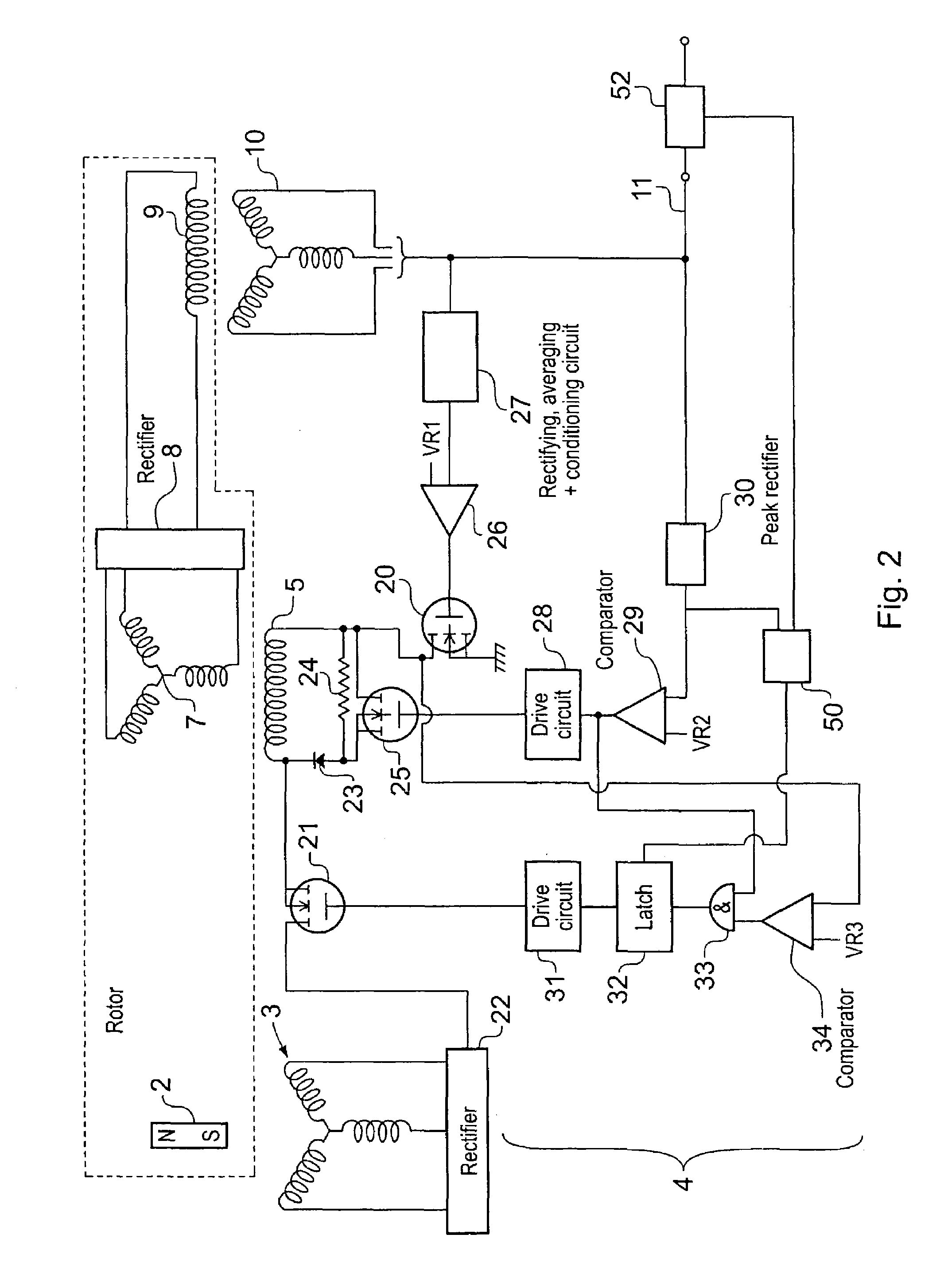
[0019]FIG. 2 shows the control unit 4 of FIG. 1 in more detail. The main exciter winding 5 has a first end thereof connected via a field effect transistor 21 to the output of a rectifier 22 which receives and rectifies the output of the permanent magnet generator stator windings 3. A second end of the main exciter stator winding 5 is connected to ground via a second field effect transistor 20. The main exciter stator winding 5 is also connected in parallel with a series circuit comprising a diode 23 and a parallel circuit comprising a resistor 24 and a field effect transistor 25.
[0020]The gate of the field effect transistor 20 is, connected to the output of a differential amplifier 26 having a first input connected to receive a first reference voltage VR1 and a second input connected to a rectifying averaging and conditioning circuit 27 which itself is connected to the generator output 11. Alternatively, RMS voltage sensing may be used as an input to the amplifier 26. The gate of tr...
PUM
 Abstract
Description
Claims
Application Information