
Probe cartridge assembly and multi-probe assembly

Inactive Publication Date: 2006-02-28
TOKYO ELECTRON LTD
View PDF6 Cites 126 Cited by
  • Summary
  • Abstract
  • Description
  • Claims
  • Application Information

AI Technical Summary

Benefits of technology

[0018]The system of the present invention advantageously provides a structure where the retaining member and the mounting member are adjustably mated to each other in order to provide a clamping force to ensure proper electrical interconnection between the electric lead, the ferrule, and the probe. When the retaining member is tightened onto the mounting member using the tool engagement portion, the retaining member and the mounting member inwardly compress the probe and the ferrule between the probe insulator and the lead insulator. The compressive forces acting on the probe and the ferrule cause the inclined surface of the probe

Problems solved by technology

In addition, each time the source is vented and physically repositioned there is a potential to introduce measurement inconsistencies due to small variations in the physical repositioning of the source, and the vertical position of the probe with respect to the chuck and the bottom of the source.

Method used


Image

  • Probe cartridge assembly and multi-probe assembly
  • Probe cartridge assembly and multi-probe assembly
  • Probe cartridge assembly and multi-probe assembly

Examples


Embodiment Construction

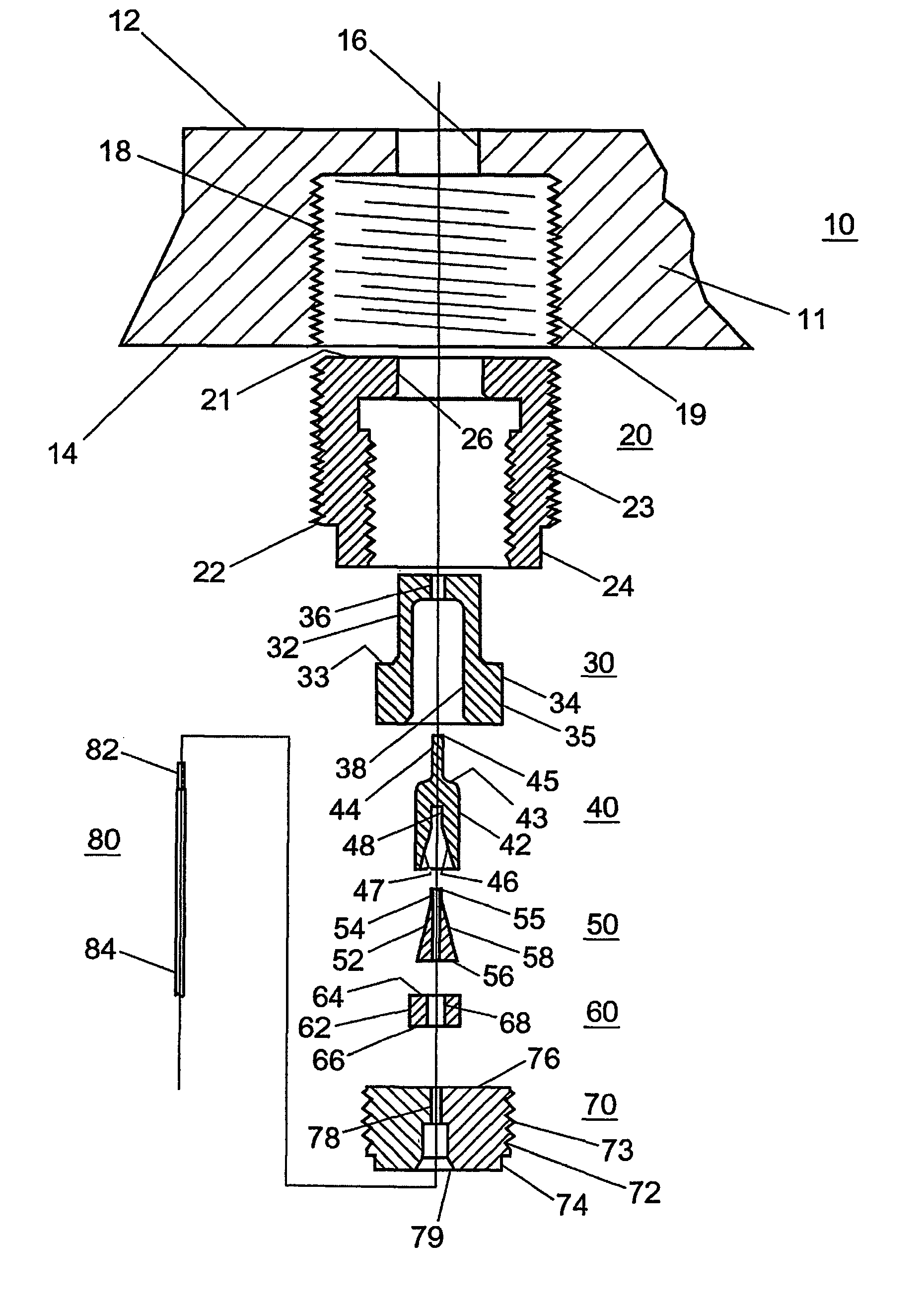
[0025]Langmuir type probes are used to measure ion current density in various plasma sources and chambers. It has been the inventors experience that it is difficult to insert more than one probe at a time into the plasma generated. Therefore, the inventors have constructed a multi-probe assembly of, for example, seventeen probes that measure ion current density at different locations in one plasma. The present invention will now be described with reference to a preferred embodiment that provides an advantageous structure that overcomes the problems identified by the inventors which are described above.

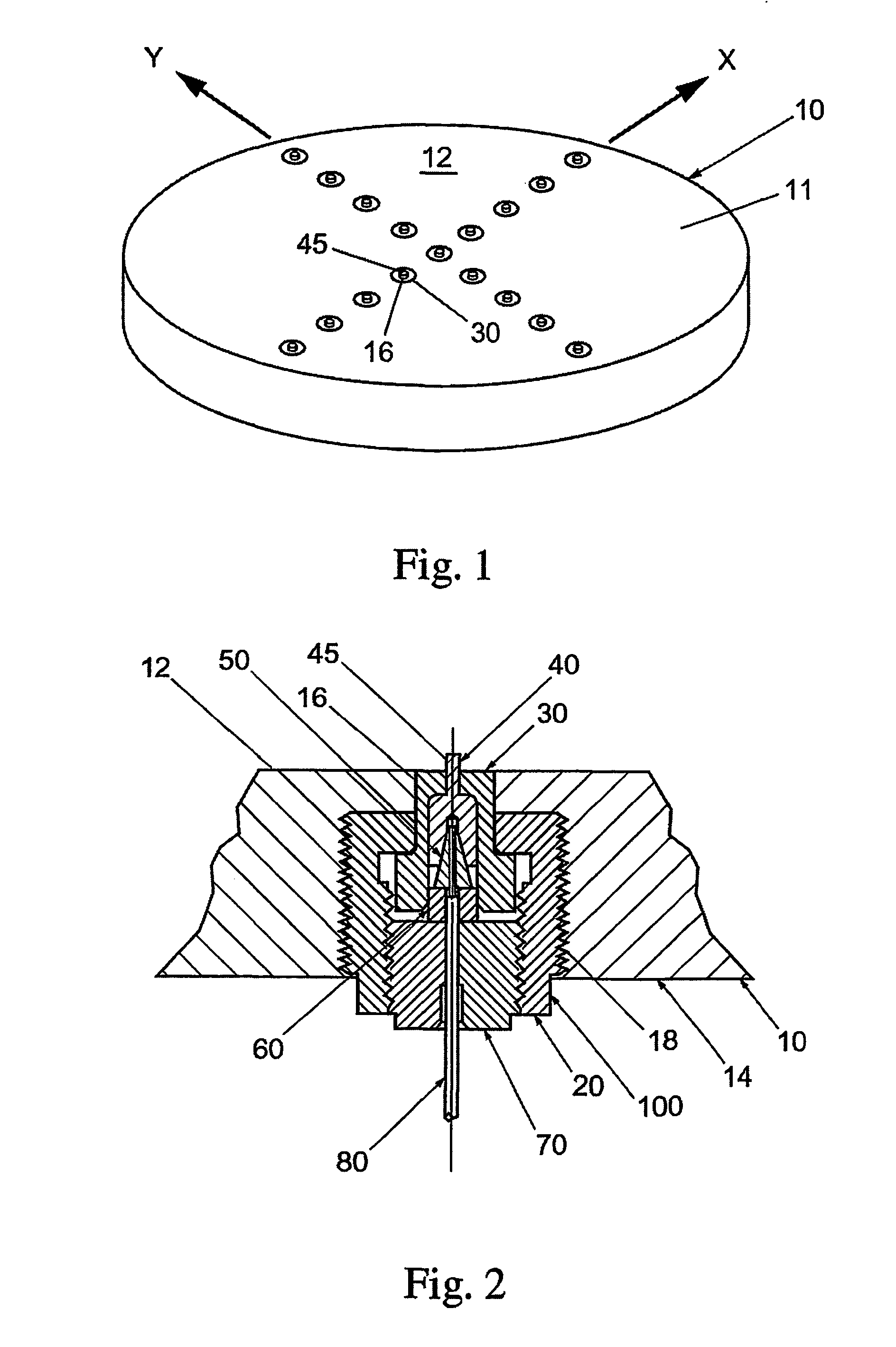
[0026]Referring now to the drawings, FIGS. 1–5 depict an embodiment of a multi-probe assembly 10 including a probe cartridge assembly 100 according to the present invention. The multi-probe assembly 10 generally includes a mounting plate 11 having a plurality of mounting holes 18 and a plurality of probe cartridge assemblies 100 each mounted in a corresponding one of the plurality of m...


PUM


Abstract

A probe cartridge assembly and a multi-probe assembly (10) including a mounting plate having a plurality of the probe cartridge assemblies mounted on the mounting plate. The probe cartridge assembly generally includes a mounting member, a probe insulator (30), a probe (40), a ferrule (50), a lead insulator (60), a retaining member (70), and a wire having an electrical lead. The electrical lead is positioned within a cavity in the ferrule, and an inclined surface of the ferrule is contacted to an inclined surface of the probe within an area defined by the probe insulator and the lead insulator. The probe insulator and the lead insulator are held within an area defined by the mounting member and the retaining member. The retaining member and the mounting member are adjustably mated to each other in order to provide a clamping force to ensure proper electrical interconnection between the electric lead, the ferrule, and the probe.

Description

CROSS-REFERENCE TO RELATED APPLICATIONS[0001]This application is a National Stage of International Application No. PCT / US01 / 45865 filed Dec. 20, 2001, which claims the benefit of U.S. Provisional Application No. 60 / 257,237 filed Dec. 22, 2000.BACKGROUND OF THE INVENTION[0002]1. Field of the Invention[0003]The present invention relates generally to a probe cartridge assembly including a probe for analyzing an environment, and a multi-probe assembly including at least one such probe cartridge assembly.[0004]2. Discussion of the Background[0005]Electric probes are measurement tools used in the characterization of low temperature plasmas like those used in the semiconductor manufacturing industry. Electric probes have been utilized in a variety of configurations and geometric shapes. Each configuration and geometry has advantages and disadvantages compared to the others. One such configuration is the single, cylindrical probe, called a Single Langmuir Probe.[0006]An example of such a si...

Claims


Application Information

Patent Timeline
IPC IPC(8): G01R31/02G01N27/00G01D11/30G01R27/00
CPCH01J37/32935G01D11/30
Inventor FINK, STEVEN T.WINDHORN, THOMAS H.
Owner TOKYO ELECTRON LTD
Features
  • Generate Ideas
  • Intellectual Property
  • Life Sciences
  • Materials
  • Tech Scout
  • Unparalleled Data Quality
  • Higher Quality Content
  • 60% Fewer Hallucinations
Learn More