Synchronous vector measuring device

a technology of synchronous vector and measuring device, which is applied in the direction of electric devices, digital computer details, instruments, etc., can solve the problems of inability to accurately measure the absolute phase angle of the object to be measured, the continuity of the absolute phase angle sub>v/sub> is lost, and the numerical stability of the numerical stability is bad

Active Publication Date: 2006-02-28
MITSUBISHI ELECTRIC CORP
View PDF10 Cites 21 Cited by
  • Summary
  • Abstract
  • Description
  • Claims
  • Application Information

AI Technical Summary

Benefits of technology

[0010]The synchronous vector measuring device according to the present invention can provide the following advantageous effects. That is, the absolute phase angle of the synchronous vector, which is obtained by using the cosine function, increases from zero degrees to plus 180 degrees, and is then inverted at that point and decreases therefrom up to zero degrees. Thus, the absolute phase angle of the synchronous vector is always a positive value, and changes continuously even at zero degrees and plus 180 degrees. As a result, there will be no discontinuous change in the absolute phase angle which would be caused in the prior art, and the amount or rate of change thereof is limited, too. Accordingly, the synchronous vector measuring device of the present invention is excellent in the numerical stability and continuity of the absolute phase angle of the synchronous vector.

Problems solved by technology

However, such a known synchronous vector measuring device, in which the absolute phase angle θv of the synchronous vector is obtained from the real part and the imaginary part of the voltage vector by the use of a tangent function, involves the following problem.
For this reason, the continuity of the absolute phase angle θv is lost, and the numerical stability thereof is bad.
In addition, there is another problem as stated below.
That is, the voltage effective value or voltage root-mean-square value of the electric power system is obtained by averaging the voltage instantaneous values within one cycle, but when the frequency of an object to be measured is different from a reference frequency, the voltage root-mean-square value and the absolute phase angle of the object to be measured cannot be correctly measured.
In particular, when an accident occurs in the electric power system, the frequency thereof varies greatly and hence the accuracy of measurements becomes worse, so the synchronous vector measured in such a situation cannot be used for urgently needed system protection control as it is.
Moreover, there is also a further problem that voltage waveform noise due to the superposition of harmonic components, a momentary drop in voltage, etc., influences the measurement result of the absolute phase angle.

Method used


Image

  • Synchronous vector measuring device
  • Synchronous vector measuring device
  • Synchronous vector measuring device

Examples


embodiment 1

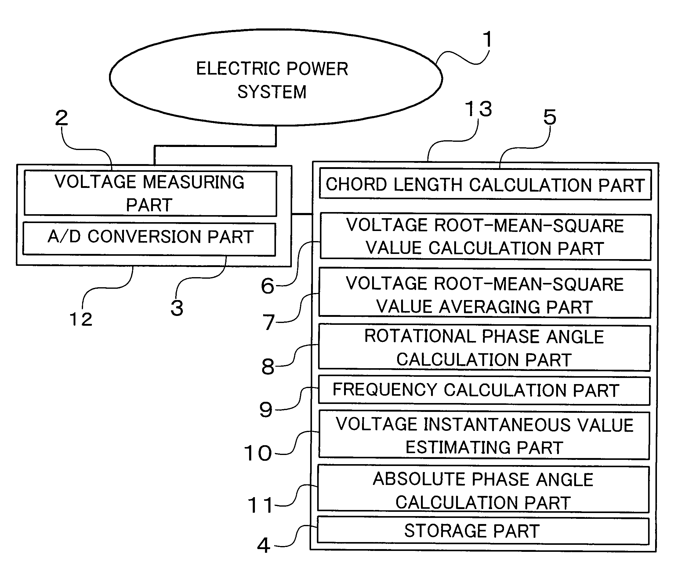
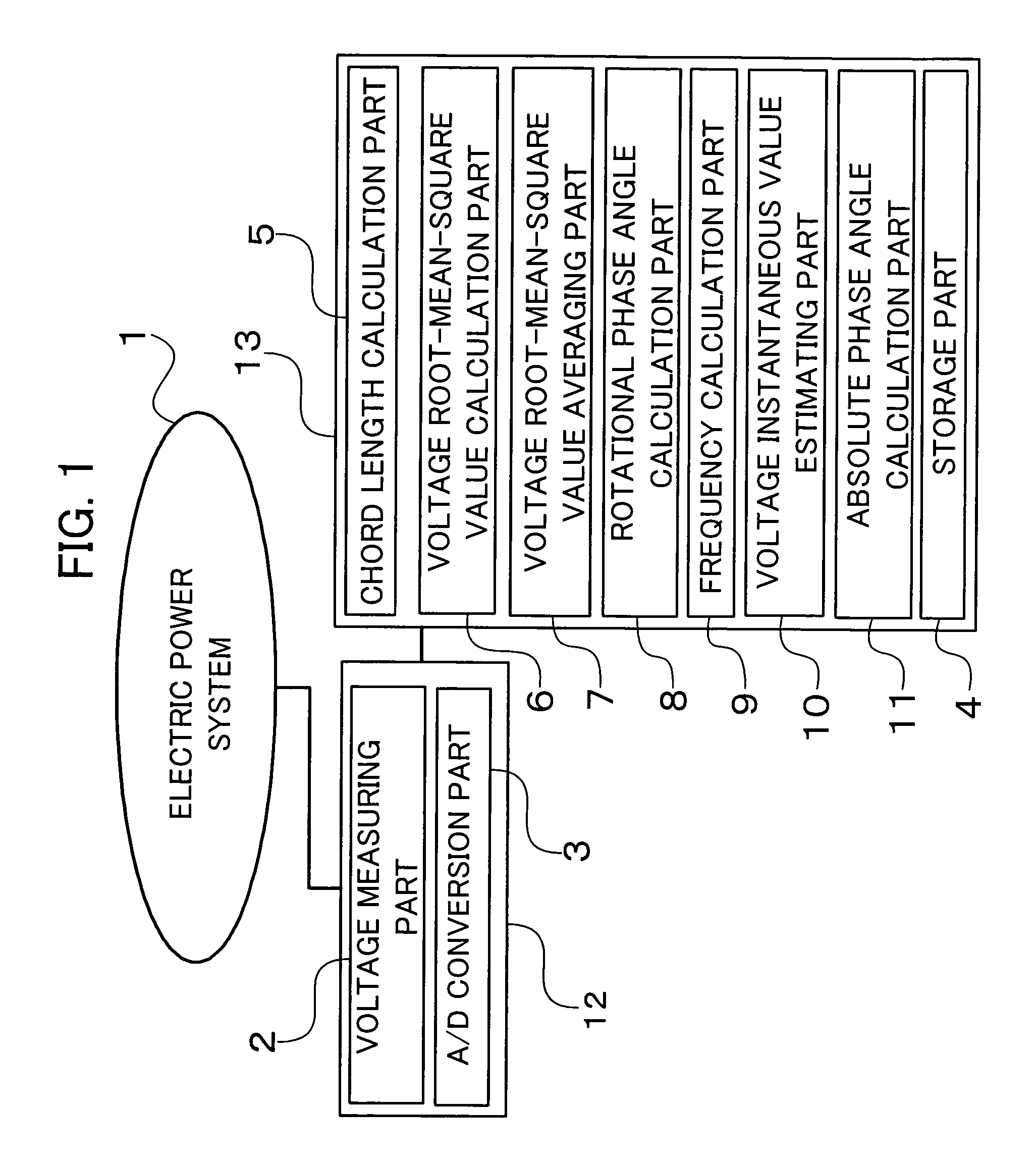
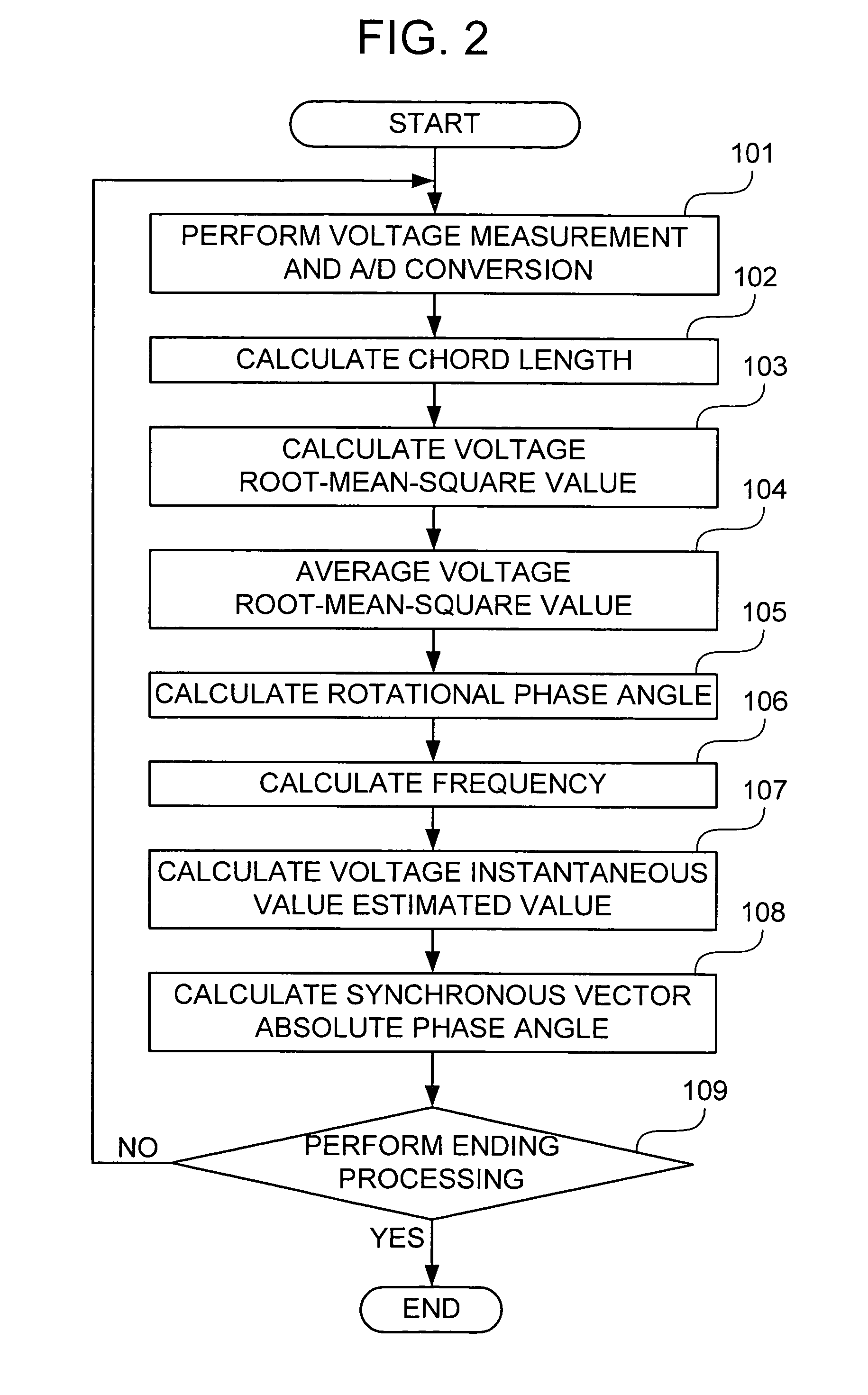
[0028]FIG. 1 is a block diagram of a synchronous vector measuring device along with an electric power system according to a first embodiment of the present invention. FIG. 2 is a flow chart showing the operation of the synchronous vector measuring device of FIG. 1 for measuring a synchronous vector of the electric power system.

[0029]The synchronous vector measuring device of this embodiment includes a voltage measuring part 2 for measuring a voltage real number instantaneous value of an electric power system 1 at each prescribed timing, an A / D conversion part 3 for converting the voltage real number instantaneous value thus measured into a digital voltage real number instantaneous value, a storage part 4 for storing the digital voltage real number instantaneous value, a chord length calculation part 5 for calculating the length of a cord formed between tip ends of adjacent rotating voltage vectors at each prescribed timing, a voltage root-mean-square value calculation part 6 for cal...

embodiment 2

[0055]FIG. 13 is a block diagram of a protection control system for an electric power system in which electric power stations and electric power substations are each provided with a synchronous vector measuring device according to a second embodiment of the present invention.

[0056]The protection control system for an electric power system includes a control unit 16 arranged at a central load dispatching center 15 for supervising and controlling the entire electric power system 1, a synchronous vector measuring device 20 provided at each of electric power stations 17 and electric power substations 18 arranged in respective places of the electric power system 1 for measuring the synchronous vector of the electric power system and sending the measured value of the synchronous vector to the control unit 16 through a network 19, and a protective relay 21 provided at each of the electric power stations 17 and the electric power substations 18 for protecting and controlling the electric po...

embodiment 3

[0059]FIG. 14 is a block diagram of a power system long-period oscillation control apparatus provided with a synchronous vector measuring device according to a third embodiment of the present invention.

[0060]The power system long-period oscillation control apparatus includes a first synchronous vector measuring device 20 for measuring a synchronous vector at an own end of a generator 22, a second synchronous vector measuring device 20 for measuring a synchronous vector of a electric power substation 18 arranged at a location remote from the generator 22, a phase difference calculation device 23 for calculating a phase difference from the absolute phase angles from the respective synchronous vector measuring devices 20, a power system stabilizer 24 for attenuating long-period oscillations of an electric power system, and an automatic voltage regulator 27 for controlling an excitation circuit 26 of the generator 22 with the use of the phase angle and the terminal voltage of the genera...


PUM


Abstract

A synchronous vector measuring device can measure an absolute phase angle of a synchronous vector excellent in continuous numerical stability at high speed and with high accuracy in a noisy electric power system. A voltage measuring part measures the voltage of the electric power system at a period equal to 1 / 4N (N being a positive integer) of one period of a reference wave. A voltage root-mean-square value calculation part calculates, at each voltage measuring timing, a voltage root-mean-square value at a specific timing from the voltages measured at past 4N timings including the specific timing. An absolute phase angle calculation part makes, at each voltage measuring timing, an inverse cosine of a value obtained by dividing the voltage measured at the specific timing by the product of the voltage root-mean-square value and the square root of 2, as the absolute phase angle of the synchronous vector at the specific timing.

Description

BACKGROUND OF THE INVENTION[0001]1. Field of the Invention[0002]The present invention relates to a synchronous vector measuring device for measuring a synchronous vector of an electric power system.[0003]2. Description of the Related Art[0004]A synchronous vector measuring device for calculating the quantity of electricity from an electric power system at high speed and with high accuracy obtains a synchronous voltage vector or phasor V by using a voltage instantaneous value Vk (k=from 1 to N) measured at N sampling timings per cycle or period based on the following expression (1). Here, note θ in the expression (1) below represents a sampling angle. Then, an absolute phase angle θv of the synchronous vector is obtained from the following expression (2) (for example, see a non-patent document: “Network Centric Approach to Protection, Control and Monitoring for Power Systems”, by K. Sekiguchi and five others, in The Institute of Electrical Engineers of Japan Transactions on Power and...

Claims


Application Information

Patent Timeline
Patent Type & Authority Patents(United States)
IPC IPC(8): G01R25/00G01R21/133G01R23/02G01R29/00G01R31/08H02H3/26H02H3/48
CPCG01R21/133
Inventor SEKI, KEMPEI
Owner MITSUBISHI ELECTRIC CORP
Why Eureka
Try Eureka