Combustion liner seal with heat transfer augmentation

a combustion liner and heat transfer technology, applied in the direction of machines/engines, stators, light and heating equipment, etc., can solve the problems of reducing overall performance and efficiency, allowing no cooling air leakage, and using more air than necessary, so as to prolong the life of the component, improve the cooling effect along the aft end of the combustion liner

Active Publication Date: 2006-03-07
H2 IP UK LTD
View PDF13 Cites 48 Cited by
  • Summary
  • Abstract
  • Description
  • Claims
  • Application Information

AI Technical Summary

Benefits of technology

[0007]The present invention seeks to provide a combustion liner having an alternate interface region between it and a transition duct where the cooling effectiveness along the aft end of the combustion liner is improved, resulting in extended component life. The combustion liner comprises a first liner end, a second liner end, and is formed from two portions, with the second portion fixed to the first portion and extending to the second end. The second portion comprises an inner liner wall, an outer liner wall, a plurality of first feed holes, a cooling ring fixed to the outer liner wall radially outward thereof and defining an annulus therebetween. The cooling ring has a cooling ring inner wall, cooling ring outer wall, and, in an alternate embodiment, further comprises a plurality of second feed holes extending therebetween. The second portion further comprises a first spring seal adjacent to the cooling ring outer wall, a second spring seal adjacent the first spring seal. Each of the first and second spring seals contain a plurality of axial slots with the slots preferably offset circumferentially. The second spring seal is positioned over the first spring seal to limit any leakage of cooling air through the plurality of first axial slots. Cooling air is directed into the annulus from first and second feed holes and across a means for augmenting the heat transfer along the outer liner wall before providing cooling to the cooling ring inner wall.
[0008]It is an object of the present invention to provide a combustion liner having an interface region with a transition duct that has improved cooling effectiveness.

Problems solved by technology

However, it is critical to only use the minimal amount of cooling air necessary to lower the operating metal temperatures of combustor 13 to within the acceptable range, and not use more air than necessary nor allow any cooling air leakage.
Seals or tight tolerances between such mating components are typically employed to overcome such leakages that can reduce overall performance and efficiency.

Method used


Image

  • Combustion liner seal with heat transfer augmentation
  • Combustion liner seal with heat transfer augmentation
  • Combustion liner seal with heat transfer augmentation

Examples


Embodiment Construction

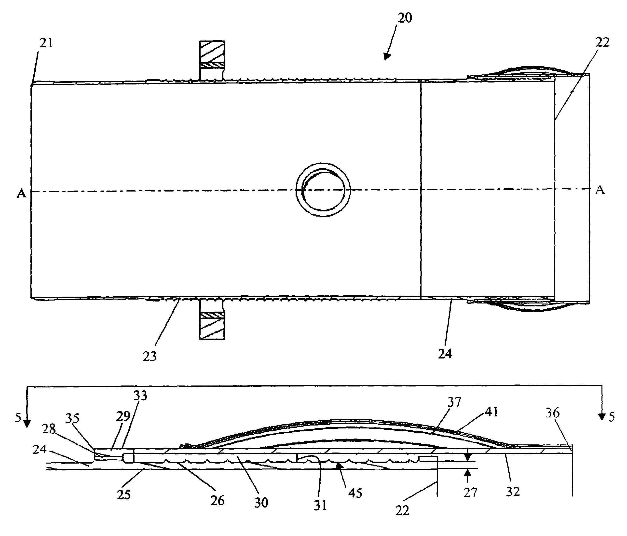
[0019]The preferred embodiment of the present invention is shown in detail in FIGS. 3–7. Referring now to FIG. 3, combustion liner 20, which is shown in cross section, interfaces with a transition duct similar to that of transition duct 14 in FIG. 1. Combustion liner 20 comprises a first end 21, a second end 22, and a centerline A—A. Located proximate first end 21 is a first portion 23 that is generally cylindrical in shape. Fixed to first portion 23 and extending towards second end 22 is a second portion 24. Second portion 24 is shown in greater detail in FIG. 4 and comprises an inner liner wall 25 and outer liner wall 26 in spaced relation to form a liner wall thickness 27. Located generally parallel to centerline A—A of combustion liner 20, in a raised section of second portion 24, is a plurality of first feed holes 28.

[0020]Second portion 24 further comprises a cooling ring 29 in fixed relation to outer liner wall 26 and located radially outward of outer liner wall 26 to thereby...


PUM


Abstract

A gas turbine combustion liner is disclosed having an alternate interface region between it and a transition duct where the cooling effectiveness and heat transfer along the aft end of the combustion liner is improved, resulting in extended component life. The region of the combustion liner proximate its second end comprises a plurality of first feed holes, a plurality of spring seals that seal against a transition duct, a cooling ring having a plurality of second feed holes, that with the first feed holes pass a cooling fluid into an annulus formed between the cooling ring and combustion liner. The cooling fluid passes over a means for augmenting the heat transfer proximate the combustion liner second end, wherein the heat transfer augmentation preferably comprises a plurality of raised ridges that increases the surface area of the outer liner wall to turbulate the cooling fluid and maximize the cooling effectiveness.

Description

TECHNICAL FIELD[0001]This invention relates in general to gas turbine engines and more specifically to the cooling and sealing arrangement of the aft end of a combustion liner.BACKGROUND OF THE INVENTION[0002]A gas turbine engine typically comprises at least one combustor, which mixes air from a compressor with a fuel. This fuel and air mixture combusts after being introduced to an ignition source. The resulting hot combustion gases pass through the combustion system and into a turbine, where the gases turn the turbine and associated shaft. A gas turbine engine is most commonly used for either propulsion for propelling a vehicle or harnessing the rotational energy from the engine shaft to drive a generator for producing electricity. Most land-based gas turbine engines employ a plurality of combustors arranged in a can-annular layout around the engine. Referring to FIG. 1, a representative land based gas turbine engine 10 of the prior art is shown in partial cross section. Gas turbin...

Claims


Application Information

Patent Timeline
Patent Type & Authority Patents(United States)
IPC IPC(8): F02C7/12F01D9/02F23R3/00F23R3/42F23R3/46
CPCF01D9/023F23R3/46F23R3/002Y02T50/675Y02T50/60
Inventor GREEN, ANDREWSTUTTAFORD, PETERBENOIT, JEFFREY ARTHURDURAIBABU, VAMSIRIZKALLA, HANY
Owner H2 IP UK LTD
Why Eureka
Try Eureka