Piston and connecting rod assembly having phosphatized bushingless connecting rod and profiled piston pin

a technology of connecting rod and piston pin, which is applied in the direction of machines/engines, detergent compositions, mechanical instruments, etc., can solve the problems of destroying the pivot point and engine failure, reducing reducing the scuff resistance of the piston pin. , to achieve the effect of prolonging the life of the relative components of the internal combustion engine, preventing seizures, and improving the scuff resistance of the piston pin

Inactive Publication Date: 2005-08-02
MAHLE TECH
View PDF28 Cites 22 Cited by
  • Summary
  • Abstract
  • Description
  • Claims
  • Application Information

AI Technical Summary

Benefits of technology

[0012]Accordingly, one advantage of the present invention is that it improves scuff resistance of a piston pin and small end connecting rod pivot point for preventing seizures at the pivot point and prolonging the life of the relative components of an internal combustion engine.
[0013]Another advantage of the present invention is that it reduces the weight of an internal combustion engine by eliminating the need for a bushing at the pivot point between the small end connecting rod small end and the piston pin.
[0014]Still another advantage of the present invention is that it reduces the cost of manufacturing a piston and connecting rod assembly by eliminating the need for a bushing at the interface between the bore of the small end of the connecting rod and the piston pin.
[0015]Still another advantage of the present invention is that it reduces the cost of assembling a piston and connecting rod assembly by eliminating the need to install a bushing within the pivot point.
[0016]Other objects, features, and advantages of the present invention will be readily appreciated, as the same becomes better understood, after reading the subsequent description taken in conjunction with the accompanying drawings.

Problems solved by technology

As a result of this deformation, the pivot point between the pin bore and connecting rod small end begins to scuff and wear.
Scuffing in this area may lead to destruction of the pivot point and engine failure.
However, bushings add weight to this pivot point and also require additional steps in manufacturing and assembly, both of which are generally undesirable.
Furthermore, in cases where bushings are not used, they are generally limited to either a diesel engine or for use with a non-profiled piston pin.
Accordingly, while the piston and connecting rod assemblies of the type known in the related art have generally worked for their intended purposes, they suffer from disadvantages relating to facilitating smooth angular movement at the pivot point while reducing weight in an internal combustion engine.

Method used


Image

  • Piston and connecting rod assembly having phosphatized bushingless connecting rod and profiled piston pin
  • Piston and connecting rod assembly having phosphatized bushingless connecting rod and profiled piston pin
  • Piston and connecting rod assembly having phosphatized bushingless connecting rod and profiled piston pin

Examples


Embodiment Construction

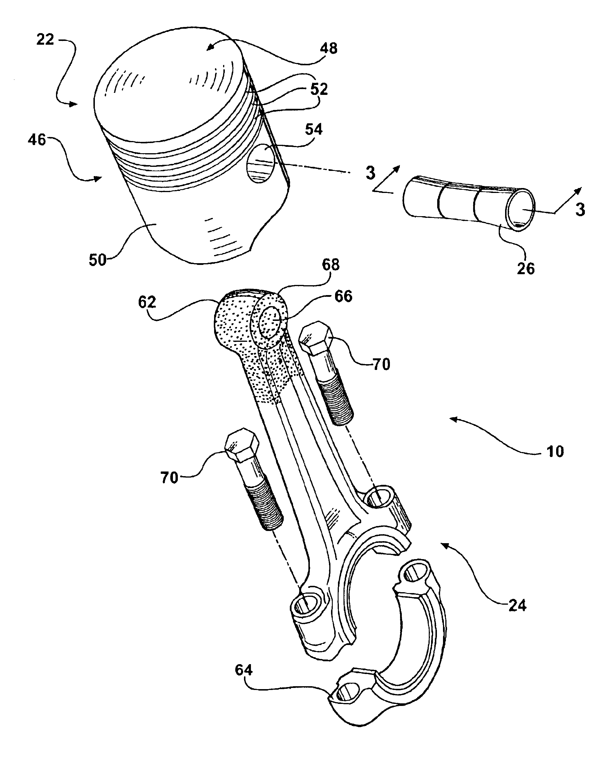
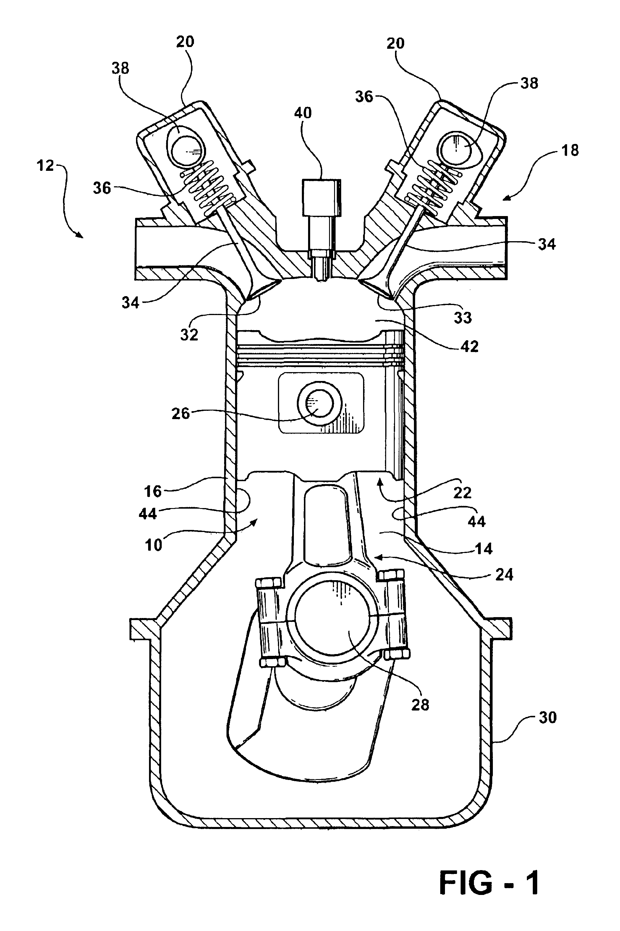
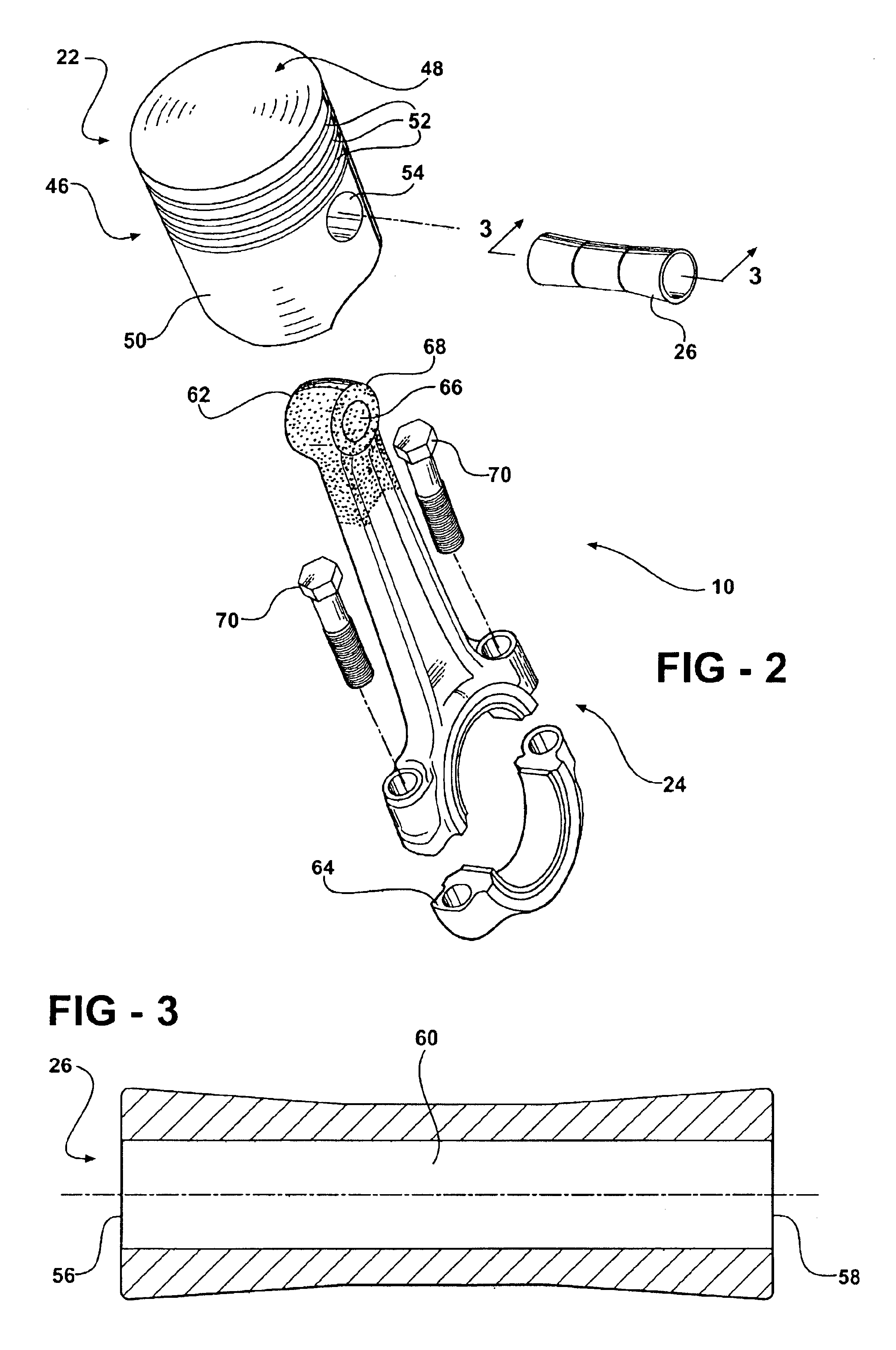
[0025]The present invention overcomes the advantages in the related art in a piston and connecting rod assembly, generally indicated at 10 and 110, in FIGS. 1-8, where like numbers are used to designate like structures throughout the drawings. As shown in FIG. 1, the present invention is particularly adapted for use in an internal combustion engine, generally indicated at 12. In this case, the assembly 10 of the present invention is illustrated in connection with a single cylinder 14 of an internal combustion engine 12 having a dual-overhead cam arrangement. Those having ordinary skill in the art will appreciate that the engine 12 is but one of the many internal combustion engines within which the present invention may be employed. By way of example, the present invention may be employed within a two-stroke or four-stroke engine. The cylinder may be arranged in an in-line, v-shaped, or flat manner or in any other manner commonly known in the art. The present invention may also be em...


PUM

PropertyMeasurementUnit
diameteraaaaaaaaaa
circumferenceaaaaaaaaaa
outer circumferenceaaaaaaaaaa

Abstract

The present invention relates to a connecting rod and piston pin assembly for an internal combustion engine to improve wear of the piston/connecting rod pivot point and reduce deformation of the pin bore. To this end, the assembly includes a piston having a pin bore, a connecting rod having a bore adapted to be aligned with the piston pin bore and piston pin interconnecting the piston and the connecting rod through engaging their respective bores. The piston pin has a profiled outer circumference that is substantially circular in cross-section with a larger diameter at the distal ends than at the center portion. One end of the connecting rod includes a phosphatized coating and is adapted to facilitate movement between the connecting rod bore and the profiled piston pin.

Description

BACKGROUND OF THE INVENTION[0001]1. Field of the Invention[0002]The present invention relates, generally, to a piston and connecting rod assembly for an internal combustion engine, and, more specifically, to such an assembly including a bushingless small-end connecting rod having a phosphatized coating for use with a profiled piston pin to improve wear of the piston / connecting rod pivot point and reduce deformation of the pin bore.[0003]2. Description of the Related Art[0004]Internal combustion engines known in the related art may generally include, among other basic components, an engine block having one or more cylinders, cylinder heads associated with the engine block and pistons supported for reciprocal movement in each cylinder. The piston generally includes a body having a crown and a skirt that depends from the crown to define the bottom half of the body of the piston. A pin bore is formed in the skirt. The pin bore corresponds to a similar bore at one end of the connecting r...

Claims


Application Information

Patent Timeline
Patent Type & Authority Patents(United States)
IPC IPC(8): B23P15/00B26D1/00C11D17/00F02B75/32B22F7/06C22C29/08
CPCB22F5/008B22F7/06B22F7/062C22C29/08F16J1/16F16J7/00B22F2998/00B22F2207/03B22F2207/13
Inventor REIN, WOLFGANGSCHNEIDER, NORBERT
Owner MAHLE TECH
Why Eureka
Try Eureka