Circulative cooling apparatus

a cooling apparatus and circuit technology, applied in the direction of cooling/ventilation/heating modification, basic electric elements, semiconductor devices, etc., can solve the problems of large power consumption, noise and vibration, affecting the operation of electronic devices, and not fully utilizing the energy utility rate of electronic devices, etc., to achieve the effect of improving the dry-out problem

Inactive Publication Date: 2006-03-07
DELTA ELECTRONICS INC
View PDF16 Cites 28 Cited by
  • Summary
  • Abstract
  • Description
  • Claims
  • Application Information

AI Technical Summary

Benefits of technology

[0014]It is therefore an objective of the present invention to provide a circulative cooling apparatus that satisfies the need to improve the dry-out problem of conventional heat pipes and vapor chambers.
[0016]In one preferred embodiments of the present inventions, a gas channel is located inside the evaporation chamber that forces the vapor of the work fluid to flow according to a direction of the gas channel. Besides the direction for vapor flow, the gas channel also enlarges the unit air pressure inside the evaporation chamber to improve the vapor flow efficiency, so as to enhance the heat dissipation efficiency of the invention.
[0017]Furthermore, the work fluid stored in the condensation chamber is a buffer for the method of two phases flow removing heat, and prevents the apparatus from drying out. In addition, in this preferred embodiment, a position of the condensation chamber is lower than a position of the evaporation chamber, and gravity thus does not slow the capillary attraction of the porous structure, thus preserving the efficiency of the invention.
[0019]The invention works on the principle of two phase flow heat removal; the thermal conductivity thereof is superior, heat response thereof is fast, and the heat transferring efficiency thereof is high. Furthermore, the invention uses the condensation chamber as storage for the work fluid, so the work fluid stored therein is a buffer to prevent the conventional drying out problem due to cooling too slowly. The operation lifetime of the invention is thereby extended. The invention also balances temperature of the chambers to decrease the spreading resistance effect.
[0020]The invention is a self-circulating cooling apparatus, and operates on its own without any additional power. Besides saving power, the invention also avoids the electronic elements attached thereto from overheating and then being burned due to the power devices or power transmission devices malfunctioning. The invention is not limited by the inner space of the system, and therefore can configure the invention according to the practical system design. Furthermore, the two chambers of the invention can be separated by a distance, so that the condensation chamber is distant from the heat source, thus enhancing the condensation efficiency of the work fluid and improving the heat dissipation efficiency of the invention.

Problems solved by technology

Energy utility rates of electronic devices are not completely utilized since a lot of energy is consumed as heat energy.
When the temperature inside the electronic system is higher than that can be tolerated by the electronic devices thereof, the physical characteristics of the electronic devices are changed by the high surrounding temperature and the electronic system becomes abnormal, generates errors, or is halted.
But disadvantages of this method are large power consumption, noise and vibration that affects operations of electronic devices.
These increase the instability between the work fluid and the vapor, and further decrease the condensed work fluid that should flow back to the evaporation section for a next evaporation procedure.

Method used


Image

  • Circulative cooling apparatus
  • Circulative cooling apparatus
  • Circulative cooling apparatus

Examples


Embodiment Construction

[0029]Reference will now be made in detail to the present preferred embodiments of the invention, examples of which are illustrated in the accompanying drawings. Wherever possible, the same reference numbers are used in the drawings and the description to refer to the same or like parts.

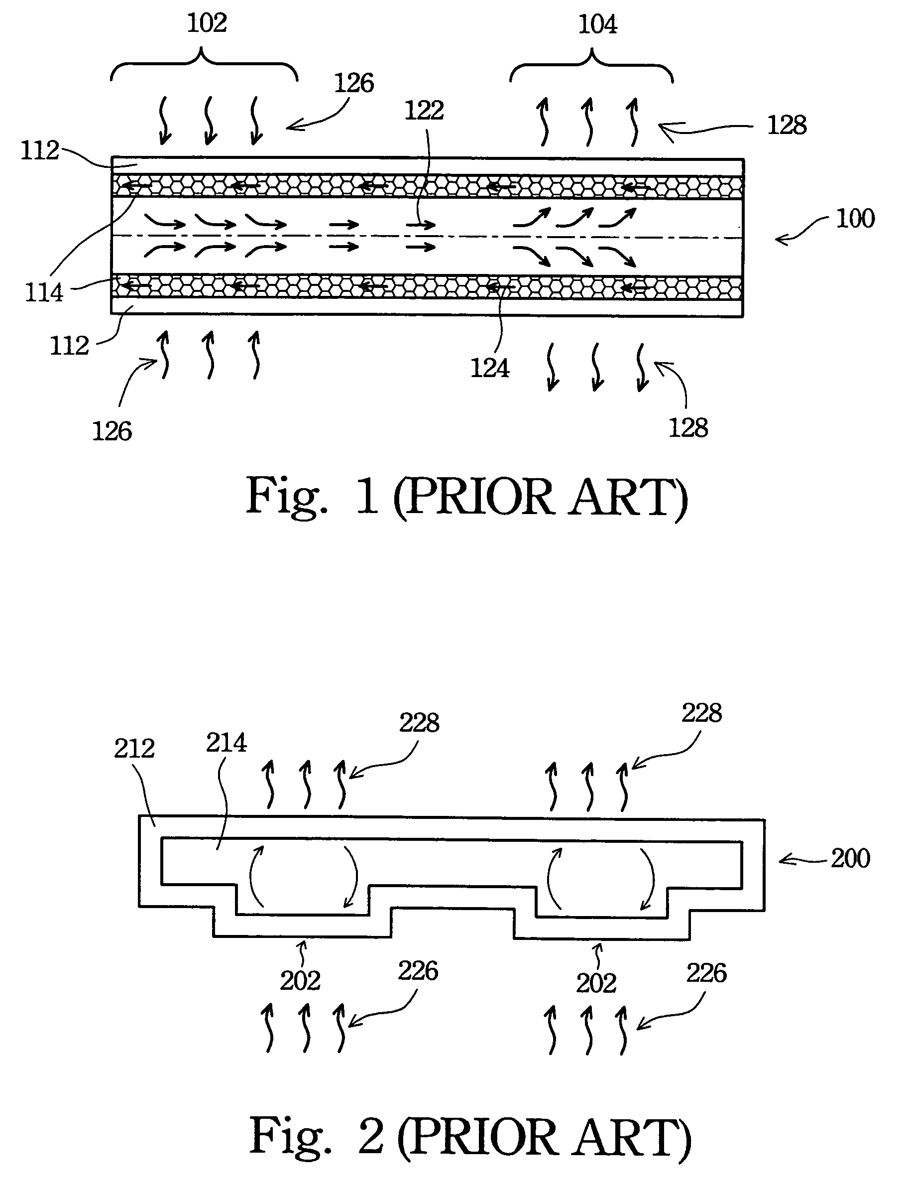
[0030]The present invention provides a circulative cooling apparatus to improve the dry-out problem of conventional heat pipes and vapor chambers.

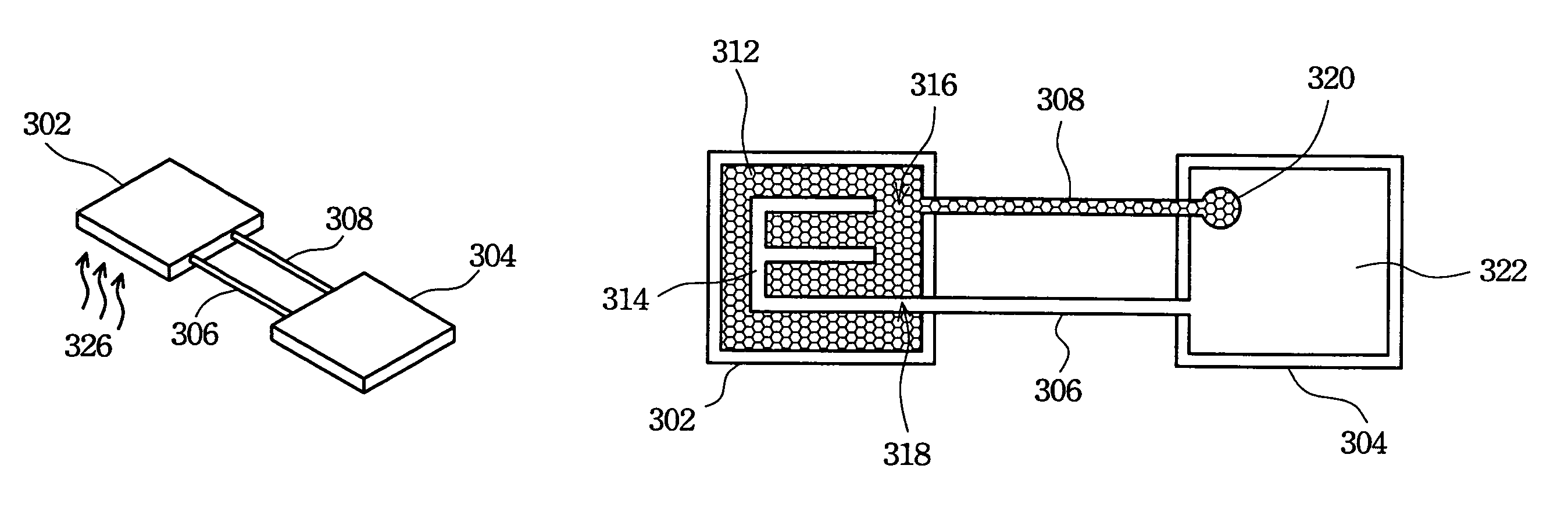
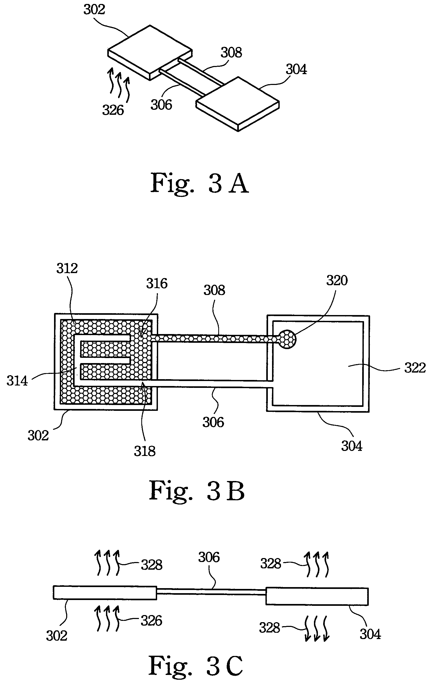
[0031]The invention provides a circulative cooling apparatus including two chambers and two pipes. An evaporation chamber receives heat energy from a heat source, and a porous structure thereof contains saturated work fluid. The work fluid is evaporated to vapor by heat energy, and owing to the pressure drop the vapor of the work fluid moves to a condensation chamber through a vapor pipe. Then the vapor of the work fluid condenses into the work fluid because of the lower temperature of the condensation chamber. The condensation chamber is storage for the wo...


PUM


Abstract

The circulative cooling apparatus has a first chamber, a second chamber, a first pipe, and a second pipe. There are porous structures on internal walls of the first chamber and the second pipe. There is work fluid in the second chamber and the porous structures. The work fluid is evaporated by heat in the first chamber, and owing to the pressure drop the vapor of the work fluid moves to the second chamber through the first pipe. Then the vapor of the work fluid condenses into the work fluid in the second chamber. Afterward the work fluid is transported back to the first chamber through the second pipe using the porous structures thereof, thus forming a circulative cooling apparatus.

Description

BACKGROUND OF THE INVENTION[0001]1. Field of Invention[0002]The present invention relates to a heat dissipation device. More particularly, the present invention relates to a circulative cooling apparatus.[0003]2. Description of Related Art[0004]Electronic devices are developed to have smaller volume, lighter weight, and lower power consumption as science and technology makes tremendous progress. Energy utility rates of electronic devices are not completely utilized since a lot of energy is consumed as heat energy. The heat energy arises a temperature inside an electronic system. When the temperature inside the electronic system is higher than that can be tolerated by the electronic devices thereof, the physical characteristics of the electronic devices are changed by the high surrounding temperature and the electronic system becomes abnormal, generates errors, or is halted. Furthermore, the temperature inside the electronic system is raised and the breakdown rate of the electronic s...

Claims


Application Information

Patent Timeline
Patent Type & Authority Patents(United States)
IPC IPC(8): F28D15/02F28D15/04H01L23/427
CPCF28D15/043H01L23/427H01L2924/0002H01L2924/00
Inventor WU, WEI-FANGHUANG, YU-HUNGCHEN, CHIN-MING
Owner DELTA ELECTRONICS INC
Why Eureka
Try Eureka