Active horizontal vibration reducing device for elevator

a technology of vibration reducing device and elevator, which is applied in the direction of elevators, building lifts, transportation and packaging, etc., can solve the problems of affecting the operation of the elevator, the degree of straightness, and the seriousness of all those factors, so as to facilitate the diagnosis

Inactive Publication Date: 2006-03-07
MITSUBISHI ELECTRIC CORP
View PDF14 Cites 17 Cited by
  • Summary
  • Abstract
  • Description
  • Claims
  • Application Information

AI Technical Summary

Benefits of technology

[0018]Due to the above arrangement, it is possible to easily make a diagnosi

Problems solved by technology

In particular, one of the important issues is how to mitigate rolling (horizontal vibrations) of the car.
Rolling of the car is attributable to an insufficient degree of straightness of the guide rails, rolling of the wire rope, fluctuations in wind pressure during the traveling of the car, etc.
All of those factors become more serious as the speed and lift of the elevator become higher.
This active type vibration reducing device, however, has a rather complicated control device including a controller, power amplifi

Method used


Image

  • Active horizontal vibration reducing device for elevator
  • Active horizontal vibration reducing device for elevator
  • Active horizontal vibration reducing device for elevator

Examples


embodiment 1

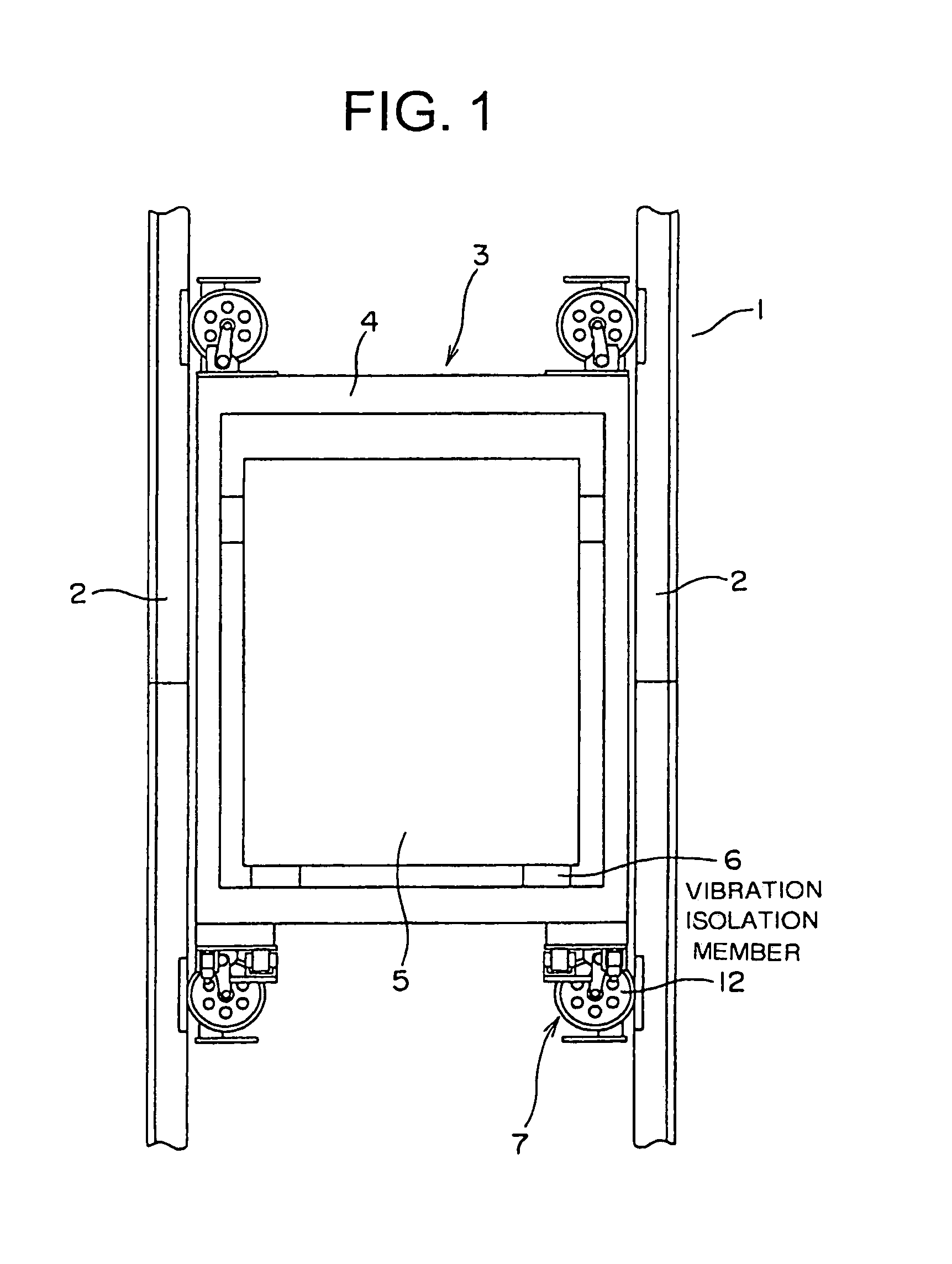
[0031]FIG. 1 is a front view of the car of an elevator according to Embodiment 1 of the present invention. In the drawing, a pair of guide rails 2 are installed in a hoistway 1. The guide rails 2 are fixed to the hoistway wall through the intermediation of brackets (not shown). A car 3 is guided by the guide rails 2 in its ascent and descent in the hoistway 1.

[0032]The car 3 has a car frame 4, a cage 5 supported by the car frame 4, and a plurality of vibration-isolating members 6 provided between the car frame 4 and the cage 5. Mounted on top of and under the car frame 4 are four roller guide devices 7. The roller guide devices 7 are engaged with the guide rails 2 to guide the car 3 in its ascent and descent.

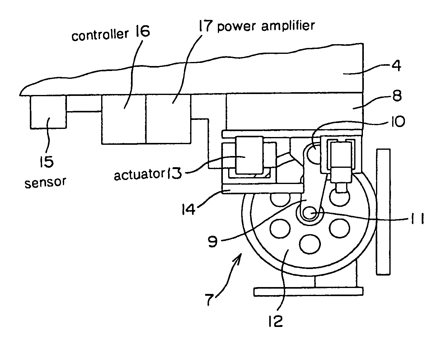
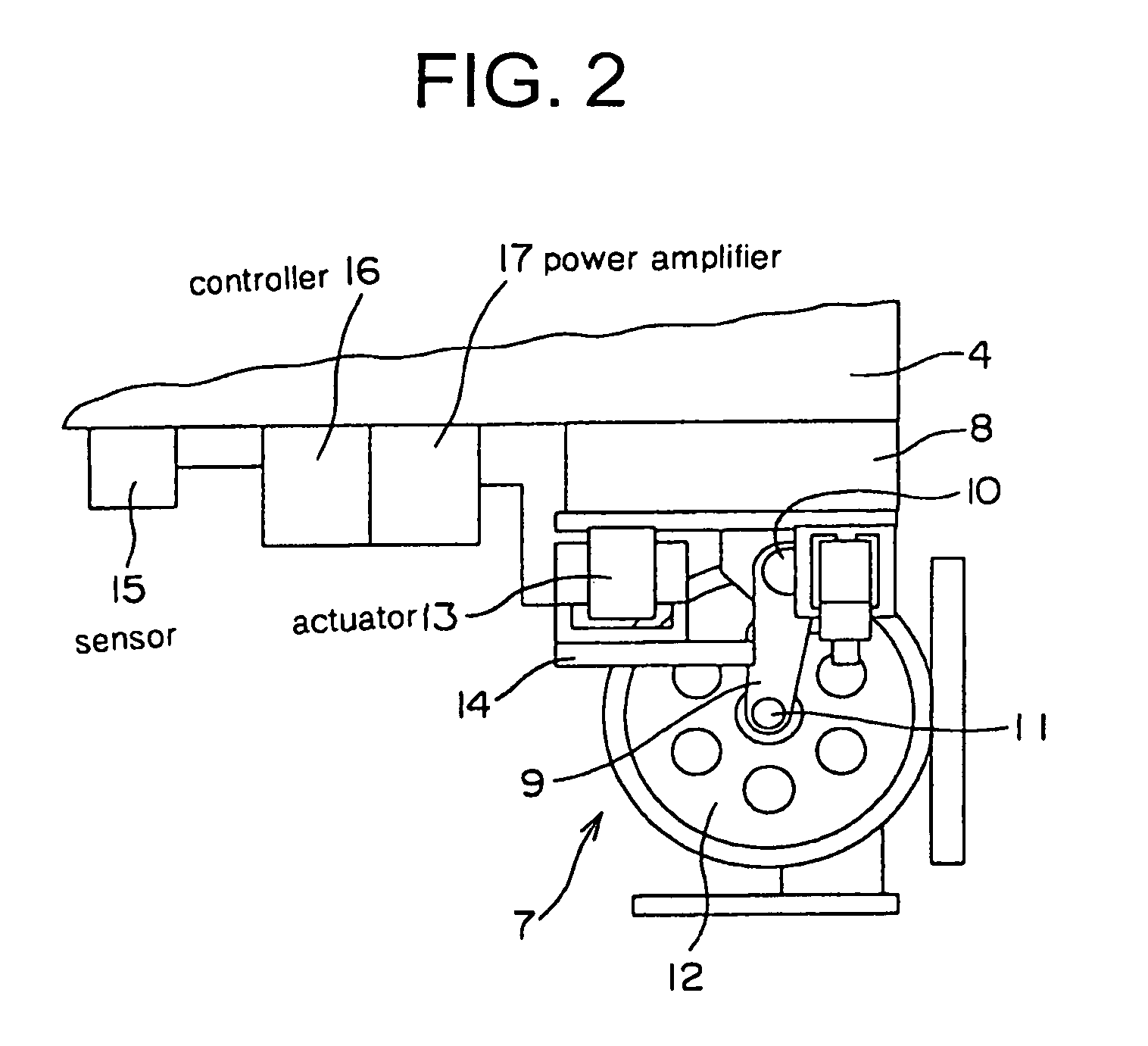
[0033]FIG. 2 is a side view of one of the roller guide devices 7 of FIG. 1. As shown in the drawing, bases 8 are fixed to the car frame 4. A plurality of roller levers 9 are respectively mounted to the bases 8. Each roller lever 9 is capable of swinging around a shaft 10 extendi...

embodiment 2

[0059]Next, FIG. 6 is a block diagram showing a main portion of a vibration reducing device according to Embodiment 2 of the present invention. In the drawing, a control portion 31 has a low-frequency band-pass filter 32, a high-frequency band-pass filter 33, a control band-pass filter 34, a first detection signal comparing portion 35, a second detection signal comparing portion 36, a third detection signal comparing portion 37, a monitoring portion 38, a computing portion 22, and an output limiter 23.

[0060]An acceleration detection signal from the acceleration sensor 15 is input to the low-frequency band-pass filter 32, the high-frequency band-pass filter 33, and the control band-pass filter 34. The low-frequency band-pass filter 32 is a band-pass filter which only allows signals of a low-frequency band (e.g., DC to 1 Hz) to pass. The high-frequency band-pass filter 33 is a band-pass filter which only allows signals of a high-frequency band (e.g., 20 Hz or more) to pass. The contro...

embodiment 3

[0070]Next, FIG. 7 is a block diagram showing a main portion of an elevator vibration reducing device according to Embodiment 3 of the present invention. In this example, there are mounted on the car 3 a plurality of acceleration sensors 15A through 15C serving as vibration sensors for detecting the accelerations of the car 3 (FIG. 1) in the same horizontal direction. A control portion 41 has a filter 18, a detection signal comparing portion 19, a counter 20, a timer 21, a computing portion 22, an output limiter 23, and a multiple sensor output comparing portion 42.

[0071]Signals from the acceleration sensors 15A through 15C are input to the multiple sensor output comparing portion 42 through the filter 18. The multiple sensor output comparing portion 42 compares the acceleration detection signals from the acceleration sensors 15A through 15C to see if there is any failure in the acceleration sensors 15A through 15C. When it is determined by the multiple sensor output comparing porti...


PUM


Abstract

An elevator vibration reducing device in which horizontal vibrations of a cage are detected by a vibration sensor. The cage is displaced horizontally by an actuator. A control portion for controlling the actuator has a computing portion for computing a vibration reduction control signal for reducing the horizontal vibrations of the cage based on a vibration detection signal generated by the vibration sensor. The control portion has a detection signal comparing portion for comparing a detection value obtained from the vibration detection signal with a previously set value, and stopping controlling of the actuator when the detection value becomes no less than the set value.

Description

BACKGROUND OF THE INVENTION[0001]1. Field of the Invention[0002]The present invention relates to an elevator vibration reducing device which actively reduces horizontal vibrations of a car in an elevator system.[0003]2. Description of the Related Art[0004]As a result of the recent increase in building height, high-speed / high-lift elevators have been developed. In such high-speed / high-lift elevators, an improvement in terms of riding comfort is among the technical concerns involved. In particular, one of the important issues is how to mitigate rolling (horizontal vibrations) of the car. Rolling of the car is attributable to an insufficient degree of straightness of the guide rails, rolling of the wire rope, fluctuations in wind pressure during the traveling of the car, etc. All of those factors become more serious as the speed and lift of the elevator become higher.[0005]To cope with this, up to now, there has been proposed a so-called active type vibration reducing device (roller gu...

Claims


Application Information

Patent Timeline
IPC IPC(8): B66B1/34B66B1/06B66B5/00B66B5/28B66B7/04B66B11/02
CPCB66B7/046B66B7/042B66B11/02
Inventor UTSUNOMIYA, KENJIOKAMOTO, KENICHIYUMURA, TAKASHI
Owner MITSUBISHI ELECTRIC CORP
Why Eureka
Try Eureka