Chemical mix and delivery systems and methods thereof

a technology of chemical mix and delivery system, applied in the direction of liquid transfer device, instrument, photosensitive material processing, etc., can solve the problems of track tool not being able to deliver photoresist when requested, bubbles may arise, imperfect images may be formed in the photolithography process,

Inactive Publication Date: 2006-03-07
AIR LIQUIDE ELECTRONICS US LP
View PDF82 Cites 23 Cited by
  • Summary
  • Abstract
  • Description
  • Claims
  • Application Information

AI Technical Summary

Benefits of technology

[0010]The present invention also may be explained by considering the problems associated with mixing and delivering slurry for chemical mechanical polishing (CMP). In semiconductor manufacturing, a slurry distribution system (SDS) delivers CMP slurry to the polisher. For example, Handbook of Semiconductor Manufacturing Technology (2000), which is incorporated by reference, describes delivery of CMP slurries to a polisher and shows an arrangement for a SDS at page 431. In some applications, the SDS needs to mix the components of the slurry in a mix tank. During mixing and handling of the slurry, the SDS must not damage the slurry by subjecting it to too much shear, which may cause aggregation, or too little shear, which may cause settling. A pump may transfer the slurry to a distribution tank when required by the process tool. The SDS should handle a variety of chemistries because a CMP slurry formulation is often tailored to each process. The SDS should introduce precise of amounts of the slurry components into a mix tank so that the slurry mixture is known. At times, there also needs to be a precise flow rate to the process tool and / or delivery at low flow rates. At low flow rates sometime microbubbles form in the dispense lines, which prevents slurry delivery. It would be desirable to clear lines without shut down of the SDS. Of course, reliability for flawlessly daily manufacturing and delivery of the slurry is also desired, as well as ease of regular maintenance to avoid varying slurry composition that may affect process results.
[0012]The present invention addresses these problems as well as avoids waste of chemicals, provides a friendly user interface depicting the amount of chemicals remaining in the supply containers, and reduces system capital and operating costs. If, for example, the amount of chemical in the supply containers cannot be seen, the present invention permits the interface to be provided at a distance by conventional computer network capabilities and the electronics provided.SUMMARY OF THE INVENTION
[0013]The present invention relates to systems using controllers or logic devices and multi-reservoir load cell assemblies for precision mixing and / or delivery of liquid chemicals. It also relates to methods of delivering liquid chemicals from supply sources to processes such that the present invention accurately accounts and adjusts for the dynamic supply and use of the liquid chemical to meet process requirements. Finally, the present invention provides multi-reservoir load cell assemblies for monitoring, regulating, and analyzing the liquid supply available to a process.

Problems solved by technology

Otherwise, the track tool will still fail to deliver the photoresist when demanded.
Thus, although the conventional system is intended to allow multiple supply containers to replenish the reservoir when needed, the system may indicate that a supply container is empty and needs to be replaced before necessary.
If this continues, bubbles may be arise due to photoresist's high susceptibility to bubbles; if a bubble, however minute, enters the photoresist delivered to the wafer, an imperfect image may be formed in the photolithography process.
Several things can happen if this persists: the lack of photoresist delivered to the track tool may send a false signal that the supply containers are empty, the pump can fail to deliver photoresist to its own internal chambers, lose its prime and ability to adequately dispense photoresist, and the pump can even overheat and burn out.
The result of each scenario will be the track tool receives insufficient or even no photoresist, known as a “missed shot,” which impacts the yield of the track tool.
Flow meters are usually only accurate to within 2–3% of the desired flow rate, and are also susceptible to changes due to input pressure.
Second, some chemicals will cause the flow meter to plug up and allow no flow, i.e. slurries.
This method also will not allow accurate flow rates, due to the potential of the push gas pressure changing, and the flow rate varying as the level within the reservoir changes.

Method used


Image

  • Chemical mix and delivery systems and methods thereof
  • Chemical mix and delivery systems and methods thereof
  • Chemical mix and delivery systems and methods thereof

Examples


first embodiment

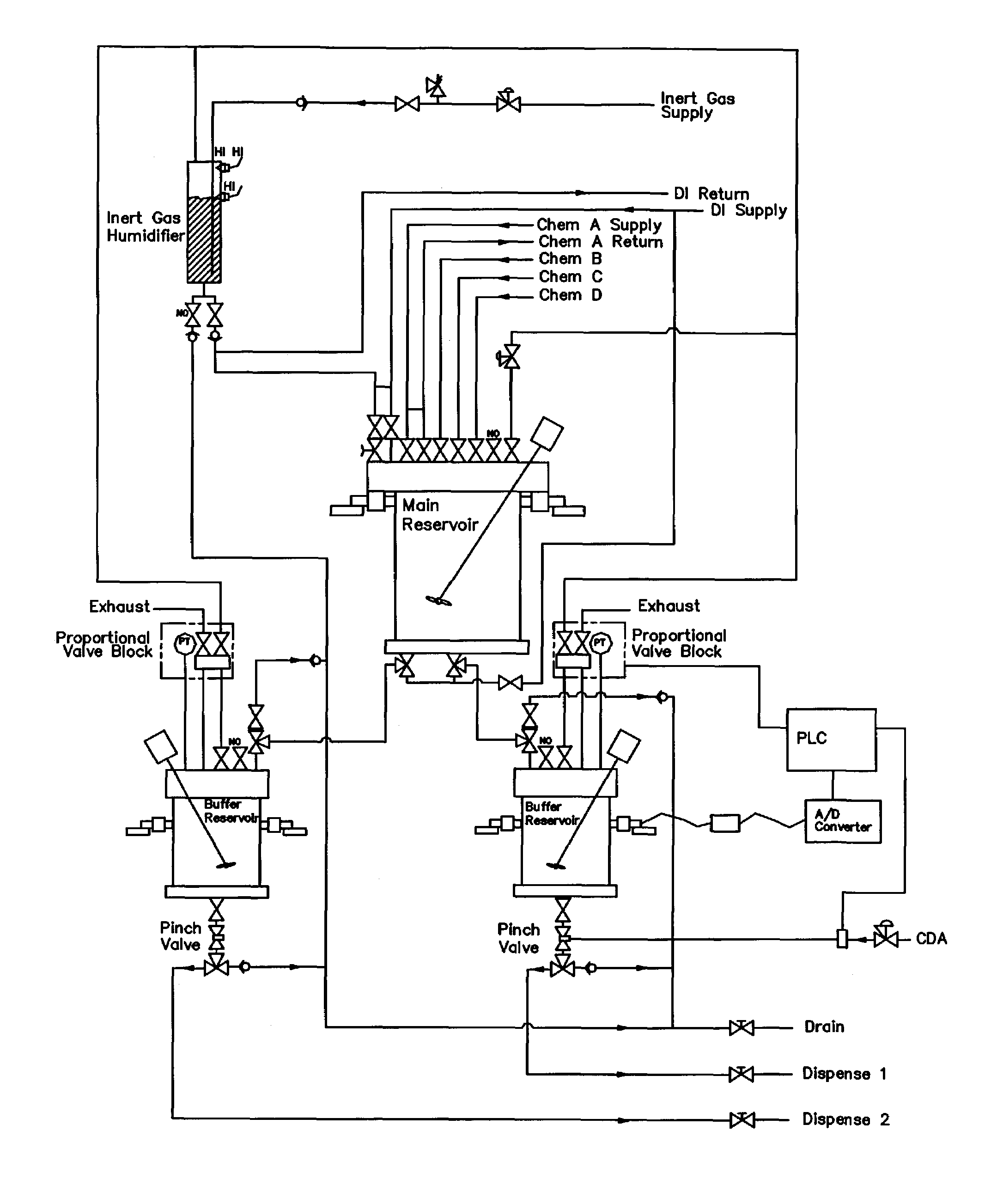
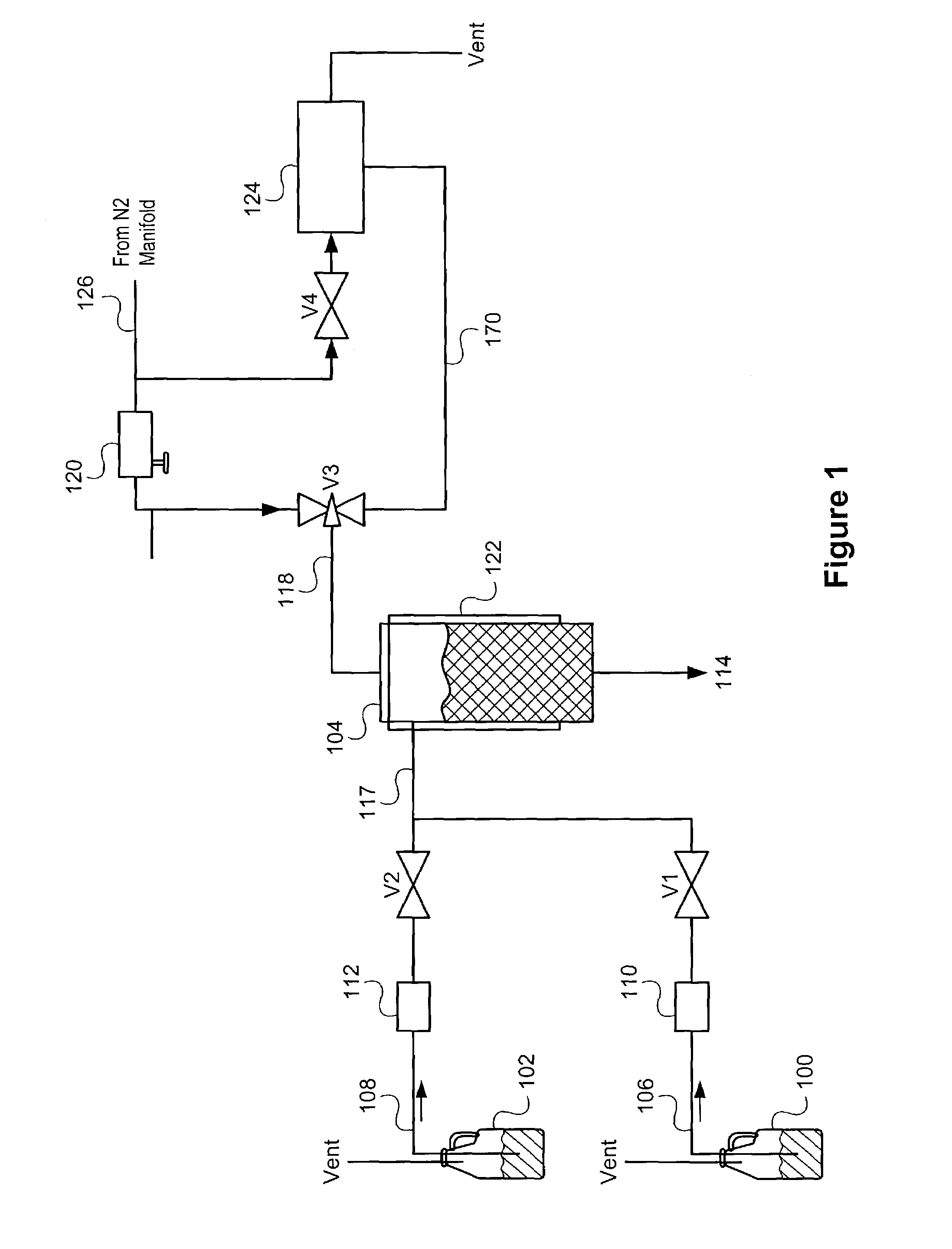
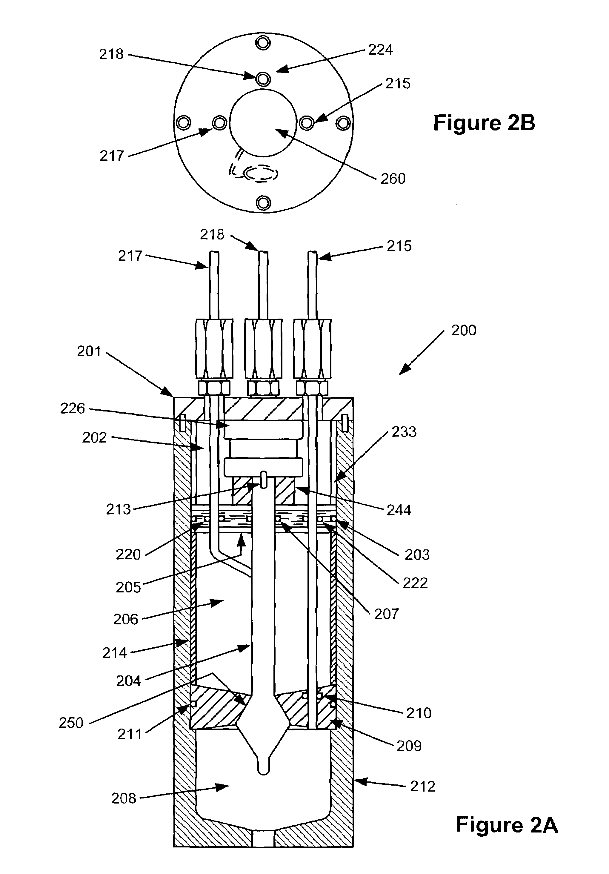
[0033]In the first embodiment, the present invention includes a multi-reservoir load cell assembly 200 as shown in FIGS. 2A–2B. The assembly 200 can be part of the system shown in FIG. 3, and can replace the problematic single-reservoir 104 and bubble sensors 110, 112 of FIG. 1.

[0034]In this embodiment, the assembly 200, constructed of Teflon, SST, polypropylene or any chemical compatible material, includes an upper compartment 202, a main reservoir 206, and a buffer reservoir 208, all in an outer housing 212. The buffer reservoir 208 is sealed from the main reservoir 206 by a separator 209, and an o-ring seal 211 seals the perimeter of the separator 209 to the outer housing 212. The separator 209 uses a center conical hole 250 that allows an internal sealing shaft 204 to form a liquid and gas-tight seal with the separator 209. The separator 209 forms a liquid and gas-tight seal to the pneumatic tube 215 with an o-ring seal 210. The main reservoir 206 contains a middle sleeve 214 th...

second embodiment

[0048]the multi-reservoir load cell assembly 400 shown in FIGS. 4A–4B, includes a buffer reservoir 408, fastened and sealed by the o-rings 411 to the bottom cap 410. The output chemical flows through tube connection 401. Connected to the buffer reservoir 408 are a pneumatic tube 415, a chemical valve 407, a load cell separator 413, and the load cell 412. The load cell 412 is securely bolted to the buffer reservoir 408 and the other side is securely bolted to a rigid member (not shown) not part of the multi-reservoir load cell assembly 400. The outer sleeve 404 slips around the buffer reservoir 408 and rests against the bottom cap 410. The outer sleeve 404 is machined to allow the load cell 412 to pass through it unencumbered. End 405 of the valve 407 connects to the main reservoir 406 and the other end 409 connects to buffer reservoir 408. The main reservoir 406 is encapsulated and sealed, by o-rings in the upper cap 403. The upper cap 403 incorporates a stepped edge along its perip...


PUM


Abstract

The present invention relates to chemical delivery systems and methods for delivery of liquid chemicals. In one embodiment, the present invention relates to systems having multi-reservoir load cell assemblies for delivering chemicals used in the semiconductor industry. In one embodiment, the present invention provides a multi-reservoir load cell assembly, including a controller, a buffer reservoir, a main reservoir, one or more load cells, coupled to the assembly and to the controller, operable to weigh the liquid in the reservoir(s), a plurality of supply lines, each supply line having a valve and connecting one of the supply containers to the main reservoir, and a gas and vacuum sources for withdrawing the liquid from the assembly when demanded by the controller and for refilling the assembly from the supply containers.

Description

BACKGROUND[0001]This application is a continuation of U.S. application Ser. No. 10 / 141,644, filed on May 6, 2002, now abandoned which is a continuation-in-part of U.S. application Ser. No. 09 / 968,566, filed on Sep. 29, 2001, now U.S. Pat. No. 6,675,987 which is a continuation of U.S. application Ser. No. 09 / 870,227, filed on May 30, 2001, now U.S. Pat. No. 6,340,098, which is a continuation of U.S. application Ser. No. 09 / 568,926, filed on May 11, 2000, now U.S. Pat. No. 6,269,975, which is a divisional of U.S. application Ser. No. 09 / 224,607, filed on Dec. 31, 1998, now U.S. Pat. No. 6,098,843, which is a continuation of U.S. application Ser. No. 09 / 222,003, filed on Dec. 30, 1998, now abandoned. This application incorporates by reference each application and each patent listed above.[0002]The present invention relates generally to systems and methods for mixing and / or delivering of liquid chemical(s), and more particularly, to systems and methods for mixing and delivering liquid c...

Claims


Application Information

Patent Timeline
Patent Type & Authority Patents(United States)
IPC IPC(8): B67D5/08B67D7/08B01F15/02B01F15/04B67D7/02B67D7/74C30B25/14G01G13/24G01G13/26G01G17/06H01L21/027H01L21/304
CPCB01F15/0266B01F15/028B01F15/0445C30B25/14B67D7/0272B67D7/0283B67D7/08B67D7/74B67D7/0238B01F2215/0036B01F2215/0096B01F35/7543B01F35/75B01F35/881B01F2101/2204B01F2101/58G03F7/26
Inventor FORSHEY, RANDYJOHNSON, KENNETH A.
Owner AIR LIQUIDE ELECTRONICS US LP
Why Eureka
Try Eureka