Fuel nozzle design

a fuel nozzle and design technology, applied in the direction of combustion types, machines/engines, lighting and heating apparatus, etc., can solve the problems of increased engine maintenance costs, undesirable engine down time, shortening the life of fuel nozzles, etc., and achieve the effect of prolonging the li

Inactive Publication Date: 2006-03-07
UNITED TECH CORP
View PDF11 Cites 28 Cited by
  • Summary
  • Abstract
  • Description
  • Claims
  • Application Information

AI Technical Summary

Benefits of technology

[0004]Accordingly, it is an object of the present invention to

Problems solved by technology

Fuel nozzles can have a shortened life span as a result of hot gases recirculating on the nozzle surface.
Such fuel nozzles are u

Method used


Image

  • Fuel nozzle design
  • Fuel nozzle design
  • Fuel nozzle design

Examples


Embodiment Construction

)

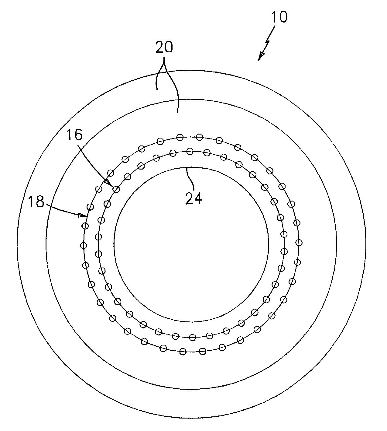
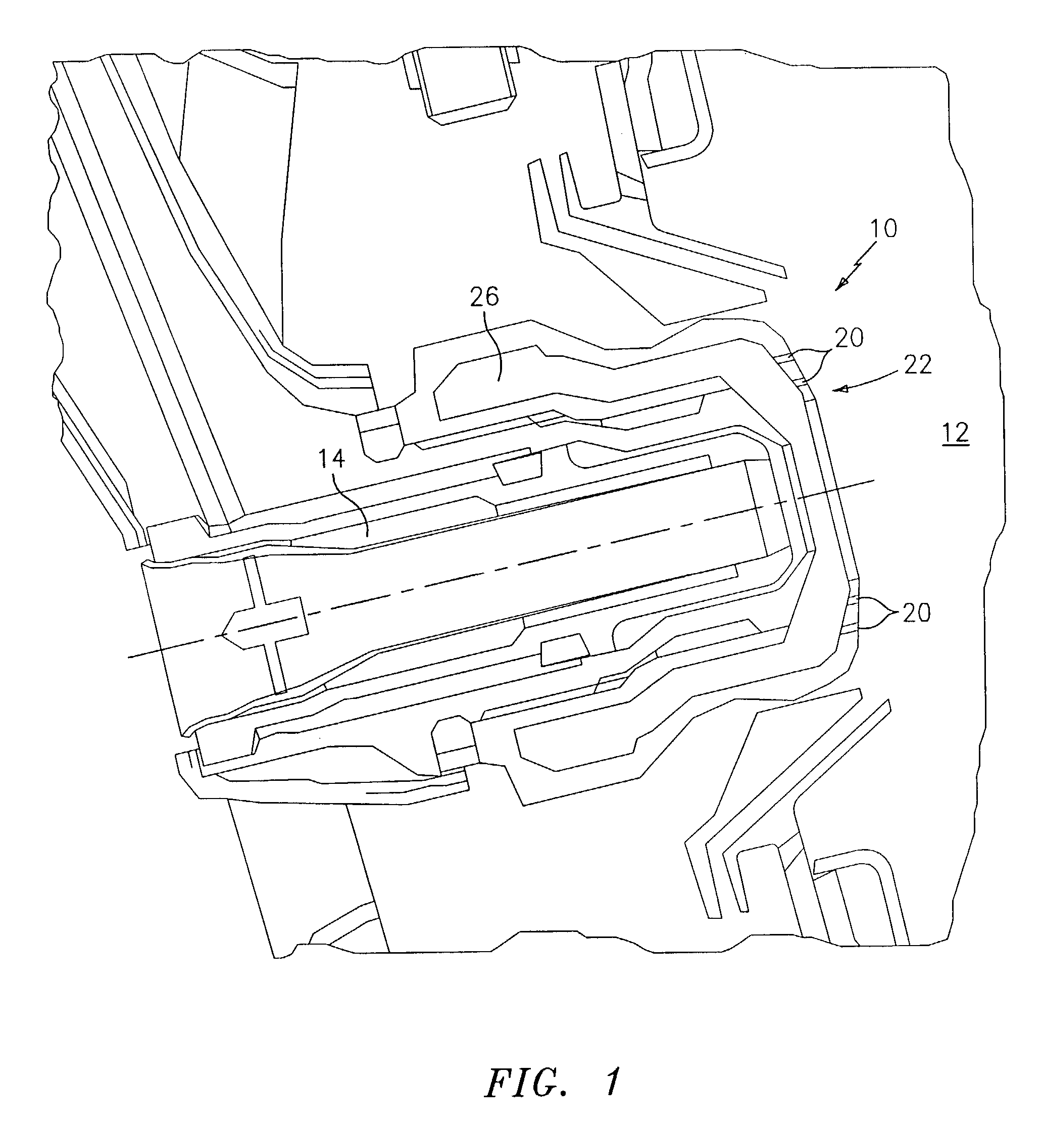
[0011]Referring now to the drawings, FIG. 1 illustrates a fuel nozzle 10 for injecting a fuel and air mixture into a combustion chamber 12 of an engine such as a gas turbine engine. The fuel nozzle 10 includes a fuel injector 14. A plurality of rows 16 and 18 of holes 20 are provided for injecting air into the combustion chamber 12.

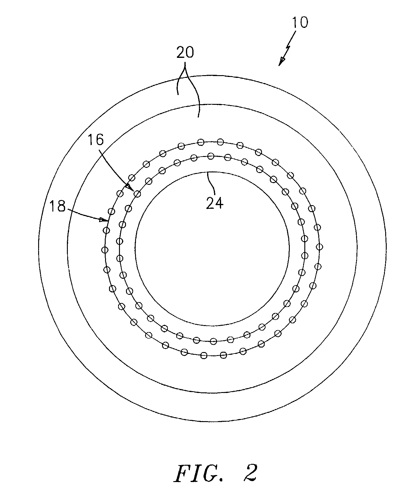
[0012]As shown in FIG. 2, the rows 16 and 18 each have a plurality of holes 20 arrayed in an annular, concentric arrangement with the holes 20 in one row being offset with respect to the holes 20 in the adjacent row. Each of the holes 20 has the same diameter and is equally spaced from its adjacent holes. In order to eliminate hot products such as hot gases from recirculating onto a face 22 of the fuel nozzle 10, the holes 20 preferably are spaced apart a distance within the range of 1.5 to 3.0 times the diameter of each hole 20. Further, the rows 16 and 18 preferably are spaced apart by a distance which is within the range of 1.5 to 3.0 times the diamet...


PUM


Abstract

The present invention relates to a fuel nozzle for use in an engine such as a gas turbine engine. The fuel nozzle includes a fuel injector for injecting fuel into a combustion chamber of the engine and a plurality of rows of holes surrounding the fuel injector for eliminating recirculation of hot gas products onto a face of the fuel nozzle. The holes eject air primarily in an axial direction.

Description

BACKGROUND OF THE INVENTION[0001]The present invention relates to a fuel nozzle design for use in a gas turbine engine which significantly extends the life of a fuel nozzle by preventing hot gases from recirculating on the nozzle surface while not adversely affecting the ignition or low emissions capability of the fuel nozzle.[0002]Fuel nozzles can have a shortened life span as a result of hot gases recirculating on the nozzle surface. Such hot gases have the opportunity of being recirculated back to the face of the fuel nozzle because of the recirculation set up between the guide swirler and the inner and outer fuel nozzle swirler. Such fuel nozzles are undesirable because they lead to increased engine maintenance costs and undesirable engine down time to replace the fuel nozzles.[0003]Thus, fuel nozzles having extended life spans are quite desirable.SUMMARY OF THE INVENTION[0004]Accordingly, it is an object of the present invention to provide a fuel nozzle which has a significantl...

Claims


Application Information

Patent Timeline
IPC IPC(8): B05B1/28F23D11/10F23D11/24F23R3/04F23R3/12F23R3/28
CPCF23D11/10F23D11/24F23R3/28F23D2900/11101F23D2900/00016
Inventor SNYDER, TIMOTHY S.HOKE, JAMES B.
Owner UNITED TECH CORP
Why Eureka
Try Eureka