Modular structures and connector assembly apparatus

a technology of modular structures and connectors, applied in the direction of scaffold accessories, washstands, light support devices, etc., can solve the problems of time-consuming and difficult manufacturing processes, inconsistent and intentional loose fittings, and lock devices, so as to avoid costly secondary forming operations and be well adapted to use

Inactive Publication Date: 2006-03-07
TURNER CAROL SUE
View PDF28 Cites 30 Cited by
  • Summary
  • Abstract
  • Description
  • Claims
  • Application Information

AI Technical Summary

Benefits of technology

[0014]The invention disclosed herein retains or even improves on the aforesaid advantages of the above connector devices and of the construction systems using them, and also overcomes all the aforesaid disadvantages.
[0015]The connector assembly described herein offers ease of manufacturing, and shipping in that it avoids costly secondary forming operations by requiring nothing of the manufacturing process beyond basic blank forming and piercing, and requires no assembly or packing of parts beyond the interchangeable, solid, one piece male and female connectors components.
[0016]The connector assembly invention disclosed herein also provides ease of assembly for the end user, requiring no tools at all. It uses no moveable part locking devices, thereby eliminating the need for pivot pins, grub screws, levers or other parts that may require manipulation and may be subject to loss or damage.
[0017]The disclosed connector assembly also retains the advantage of “looseness” in the first stages of assembly, making for easier use in the initial stage of fitting components together, but upon completion of assembly, connector components automatically lock tightly and precisely into place. Therefore, the overall structural dimensions produced are more consistent than was possible with previous art.
[0018]Additionally, the connector assembly disclosed herein does not suffer from the tendency to become more loose and weak with time and use as did earlier art. Instead, the connector components tend to become stronger and more securely joined as time passes and usage continues. This is because the assembly is so oriented as to use gravity and loads as means of fixing its components together. As vertical load is applied to the assembled components, they become more tightly and rigidly united. However, the connectors can be easily un-mated as necessary, making them particularly well adapted to use for “knock down” structures.
[0019]Finally, the disclosed connector assembly can easily join together wide flat surfaces, face to face, in contrast to previous art, that cannot.

Problems solved by technology

In such designs, the fits and tolerances are consistently and intentionally very loose.
However, in each case, these necessarily loose fits and manufacturing tolerances associated with each connector create significant disadvantages.
One such disadvantage is that in many of them, locking devices, such as pivot pins, grub screws, levers and the like, must be used to finally, securely and rigidly mate opposing connector parts together.
Often, these locking devices must be installed using hand tools, a process that may be time-consuming and challenging for the manufacturer or for the do-it-yourself customer.
Furthermore, the extra parts required may be lost or damaged during the shipping or assembly.
Another disadvantage is that the “looseness” inherent to these systems requires that construction systems using these connectors sacrifice strength, rigidity and resiliency to achieve ease of assembly.
They may not be dimensionally consistent at all joints.
Therefore, the overall lengths that result from joining several structural components may vary unpredictably.
This renders them unsuited for use in building complex structures such as residential decks, with rails and stairs, particularly those capable of repeated assembly and disassembly by hand without the use of tools.
Such connectors also tend to become progressively looser, weaker, and less rigid when subjected to loads and vibrations.
Moreover, such structures cannot comply with strict construction safety standards as are demanded for residential use.
Further, although the connector parts and their associated locking devices may be designed with loose tolerances, they are still complex to manufacture and assemble, requiring secondary forming operations and assembly, and / or separate packing of multiple parts.
Finally, of the prior art, no trapezoidal slide based design is capable of rigidly joining faces of two opposing parts.

Method used


Image

  • Modular structures and connector assembly apparatus
  • Modular structures and connector assembly apparatus
  • Modular structures and connector assembly apparatus

Examples


Embodiment Construction

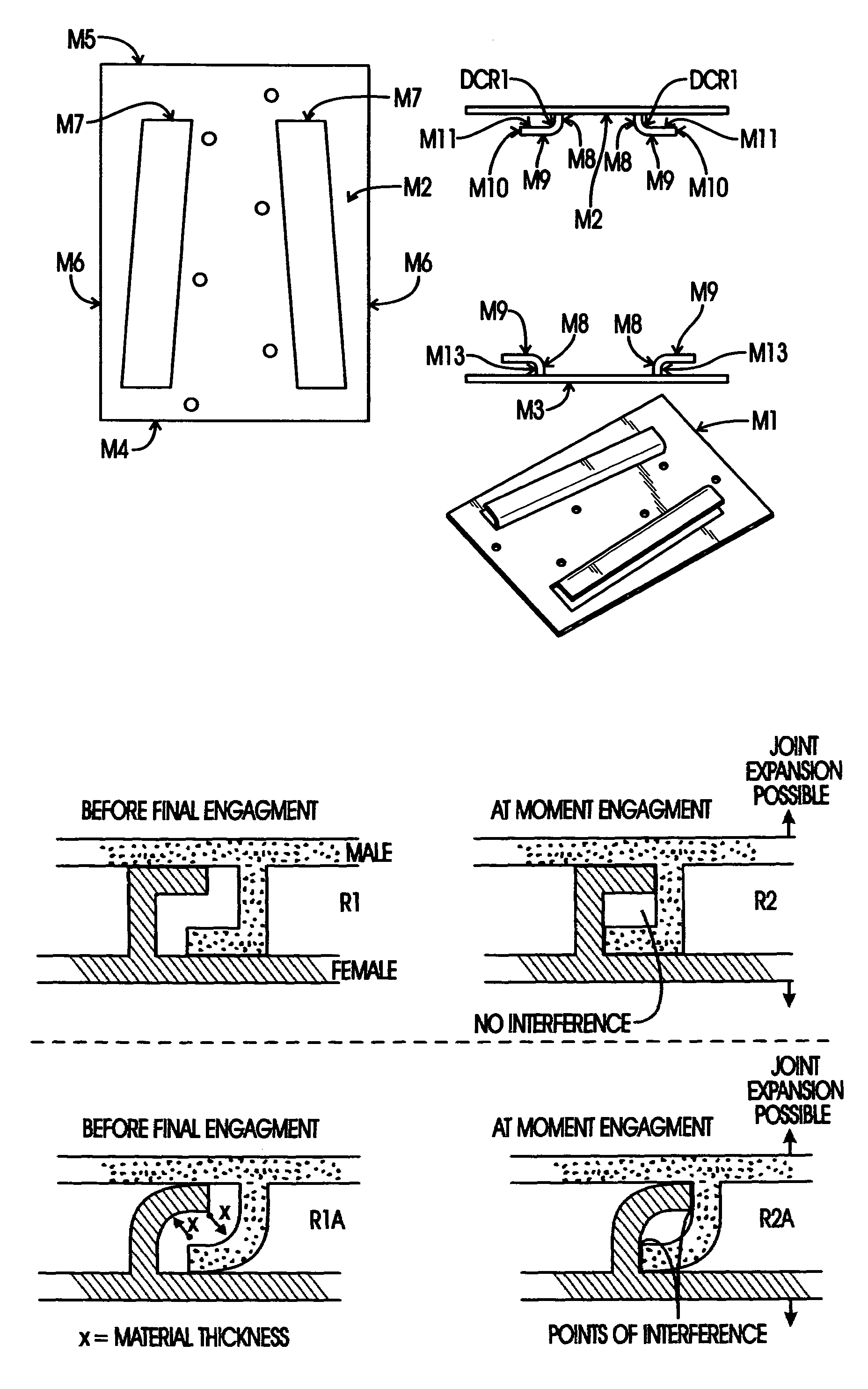
[0077]In the following descriptions when referring to connectors, the terms “top” and “bottom” are arbitrary and used only as a means of orienting the reader. In actual operation either end of the connector assembly may be used in the superior position, so long as the male and female components are matched in orientation.

[0078]Disclosed herein is a Modular Construction System (MCS) driven by multiple parameters. The resultant structure must, and does, comply with International Building Code standards for residential structures, where applicable. The resultant structure must be, and is, tight and rigid when fully assembled. The resultant structure must be, and is, quickly and easily assembled without tools. The connector assembly must be, and is, sufficiently precise to permit building extended and complex structures capable of disassembly and reassembly. Finally, the components must be, and are, capable of efficient manufacture to ensure their affordability.

[0079]As disclosed herein...


PUM

PropertyMeasurementUnit
lengthaaaaaaaaaa
thicknessaaaaaaaaaa
dimensionsaaaaaaaaaa

Abstract

Disclosed is a modular, knock down structure construction system illustrated by three structures, each having connecting portions detachably secured to one another by Trapezoidal Quick Slide Connector Assemblies, also disclosed, that enable a user to erect, without tools, a pre-designed structure.
Additionally disclosed is a manufacturing apparatus for accurately and efficiently mounting connector assemblies on structural parts for later assembly.

Description

CROSS-REFERENCE TO RELATED APPLICATIONS[0001]This application relates to and claims the benefit of U.S. Provisional Application No. 60 / 380,465 filed 15 May 2002 by Mr. Jerry R. Turner with respect to the disclosed trapezoidal quick slide connectors and modular knock down structure construction system for a residential deck system.FEDERALLY SPONSORED RESEARCH[0002]Not ApplicableINCORPORATION-BY-REFERENCE OF MATERIAL SUBMITTED ON A COMPACT DISK[0003]Not ApplicableBACKGROUND OF THE INVENTION[0004]1. Field of Invention[0005]The field of the invention relates generally to connector assemblies used to construct appliances and structures, and more particularly to a sliding connector assembly for rigid construction of prefabricated structures.[0006]2. Related Art[0007]Various types of connector assemblies are known and used in construction of appliances and structures to provide releasable connections between one or more structural components. For example, pin and slot connectors have been ...

Claims


Application Information

Patent Timeline
Patent Type & Authority Patents(United States)
IPC IPC(8): A47B96/06A47B83/02B32B7/12E04B1/00E04F13/18E04F15/10F16B12/20
CPCA47B83/02B32B7/12E04B1/003F16B12/20E04F13/18E04F15/10E04B2001/2628E04F2203/04E04F2290/023E04B2001/2632A47B3/06Y02B30/00E04B1/00
Inventor TURNER, JERRY RANDALL
Owner TURNER CAROL SUE
Why Eureka
Try Eureka