
Utility vehicle windscreen system

a technology for windscreens and utility vehicles, applied in the field of utility vehicles, can solve the problems of reducing the protection of the driver and passengers from debris, and reducing the airflow into the cab area, so as to reduce the accumulation of dust, easy to clean, and easy to install and remov

Inactive Publication Date: 2006-03-07
SCHNELLER DANIEL P
View PDF20 Cites 12 Cited by
  • Summary
  • Abstract
  • Description
  • Claims
  • Application Information

AI Technical Summary

Benefits of technology

[0011]To attain this, the present invention generally comprises a windscreen and a plurality of brackets. The brackets are attached to the front portion of the roll cage of the utility vehicle and the windscreen is attached to the brackets to provide protection to the driver and passengers from debris.
[0015]A second object is to provide a utility vehicle windscreen system for providing protection from debris to a utility vehicle driver while allowing airflow into the cab area.
[0016]Another object is to provide a utility vehicle windscreen system that reduces the accumulation of dust and debris within the cab area while protecting the driver and passengers.
[0017]An additional object is to provide a utility vehicle windscreen system that is easy to install and remove with most conventional utility vehicles.
[0018]A further object is to provide a utility vehicle windscreen system that is easy to clean and that is capable of being rolled up into a compact storage position.
[0020]A further object is to provide a utility vehicle windscreen system that does not need to be removed when the utility vehicle is towed at high speeds upon a trailer.

Problems solved by technology

One of the problems with conventional utility vehicles is that they do not protect the driver and passengers from debris (e.g. bugs, rocks, branches).
However, these transparent devices reduce the passage of air into the cab area.
In addition, during warm and hot weather conditions, reduced airflow into the cab area can be uncomfortable for the driver and passengers.
While utility vehicles are suitable for the particular purpose to which they address, they are not as suitable for providing protection from debris to a driver while allowing airflow into the cab area.
Conventional utility vehicles do not provide adequate protection for drivers and passengers.

Method used


Image

  • Utility vehicle windscreen system
  • Utility vehicle windscreen system
  • Utility vehicle windscreen system

Examples


Embodiment Construction

A. Overview

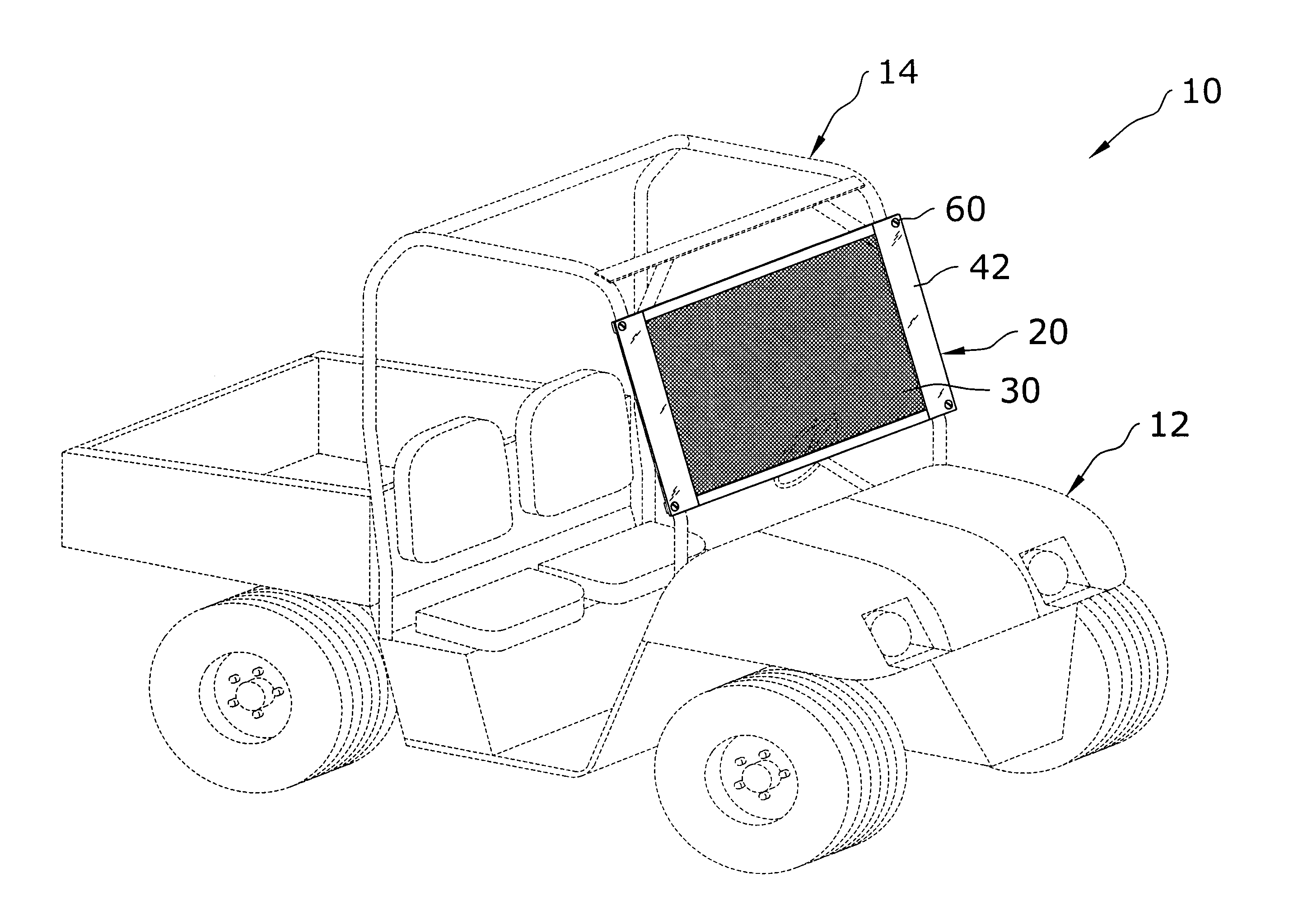
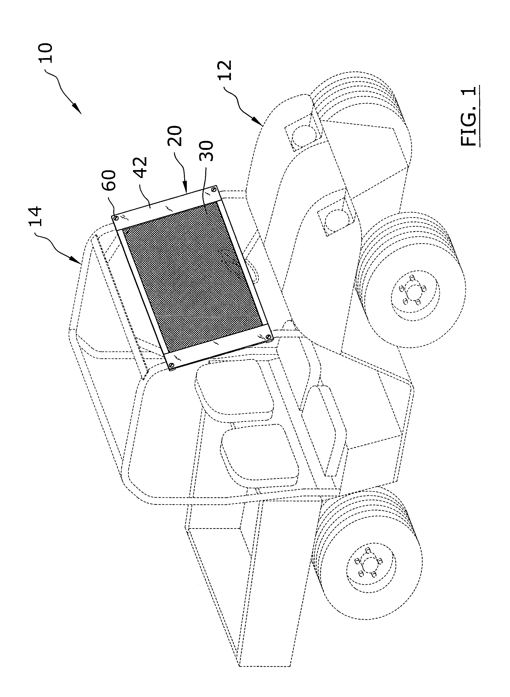
[0030]Turning now descriptively to the drawings, in which similar reference characters denote similar elements throughout the several views, FIGS. 1 through 6 illustrate a utility vehicle windscreen system 10, which comprises a windscreen 20 and a plurality of brackets 50. The brackets 50 are attached to the front portion of the roll cage 14 of the utility vehicle 12 and the windscreen 20 is attached to the brackets 50 to provide protection to the driver and passengers from debris.

B. Brackets

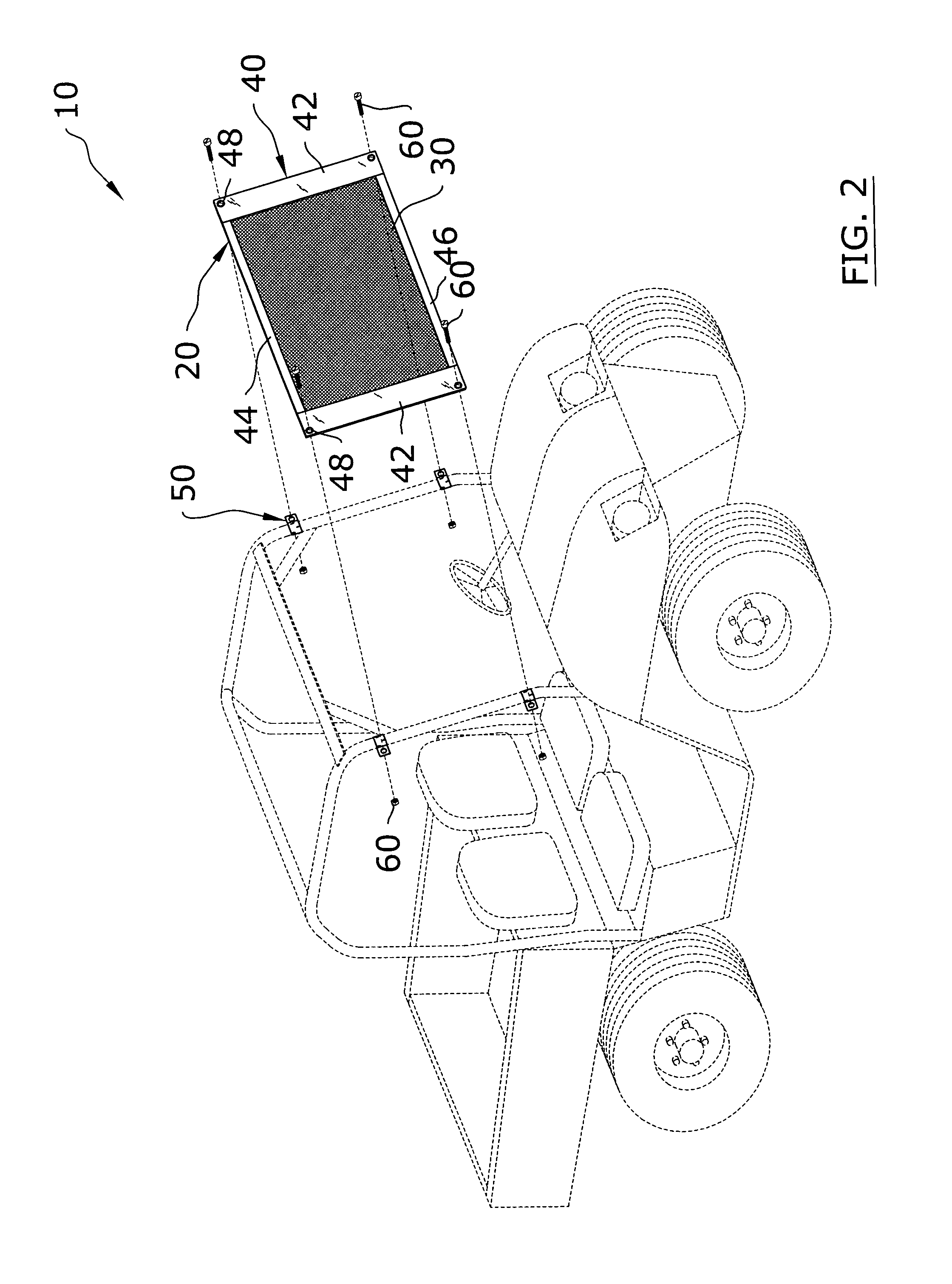
[0031]The plurality of brackets 50 are attachable to a pair of front posts of a roll cage 14 of a utility vehicle 12 as best illustrated in FIG. 2 of the drawings. As further shown in FIG. 2 of the drawings, there are preferably four brackets 50 attached to roll cage 14 for retaining each of the four corners of the windscreen 20, however more or less brackets 50 may be utilized with the present invention.

[0032]Each of the plurality of brackets 50 are preferably comprised of a cuff-lik...


PUM


Abstract

A utility vehicle windscreen system for providing protection from debris to a utility vehicle driver while allowing airflow into the cab area. The utility vehicle windscreen system includes a windscreen and a plurality of brackets. The brackets are attached to the front portion of the roll cage of the utility vehicle and the windscreen is attached to the brackets to provide protection to the driver and passengers from debris.

Description

CROSS REFERENCE TO RELATED APPLICATIONS[0001]Not applicable to this application.STATEMENT REGARDING FEDERALLY SPONSORED RESEARCH OR DEVELOPMENT[0002]Not applicable to this application.BACKGROUND OF THE INVENTION[0003]1. Field of the Invention[0004]The present invention relates generally to utility vehicles and more specifically it relates to a utility vehicle windscreen system for providing protection from debris to a utility vehicle driver while allowing airflow into the cab area.[0005]2. Description of the Related Art[0006]Utility vehicles (e.g. POLARIS RANGER) are becoming increasingly popular. An exemplary utility vehicle is illustrated in FIG. 2 of the drawings which is comprised of a body, a cab area where the driver is seated and a roll cage that surrounds the cab area. One of the problems with conventional utility vehicles is that they do not protect the driver and passengers from debris (e.g. bugs, rocks, branches).[0007]Cab enclosures and lightweight transparent windshield...

Claims


Application Information

Patent Timeline
Patent Type & Authority Patents(United States)
IPC IPC(8): B60J1/02
CPCB60J1/02
Inventor SCHNELLER, DANIEL P.
Owner SCHNELLER DANIEL P
Learn More