

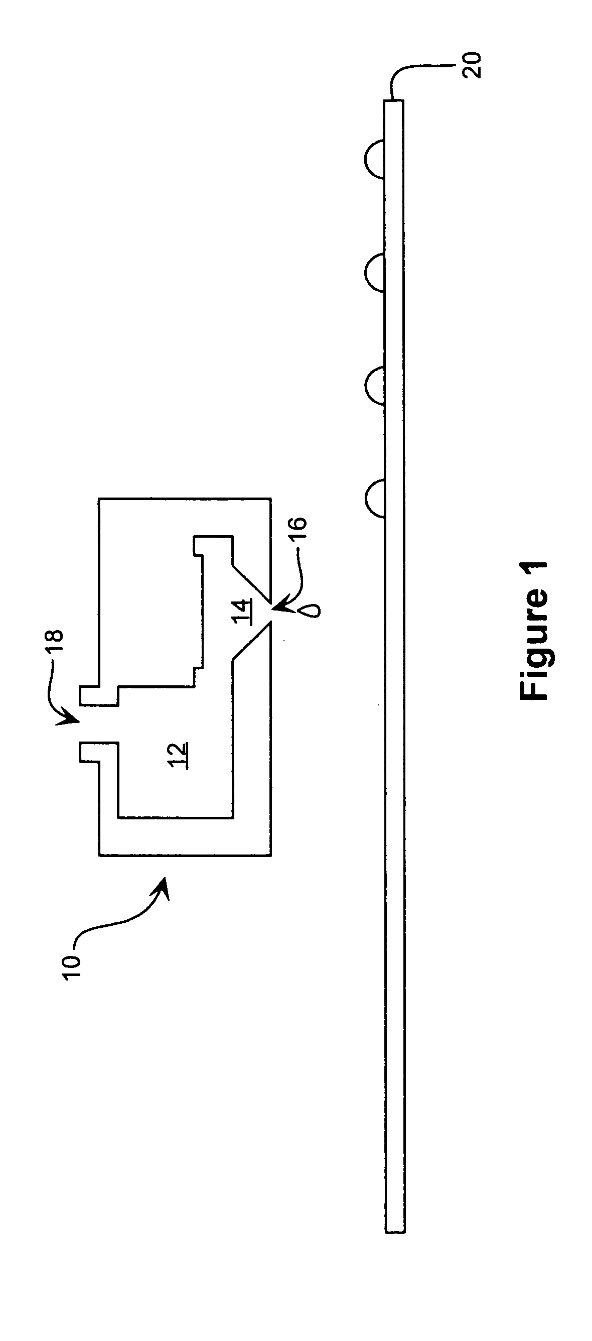
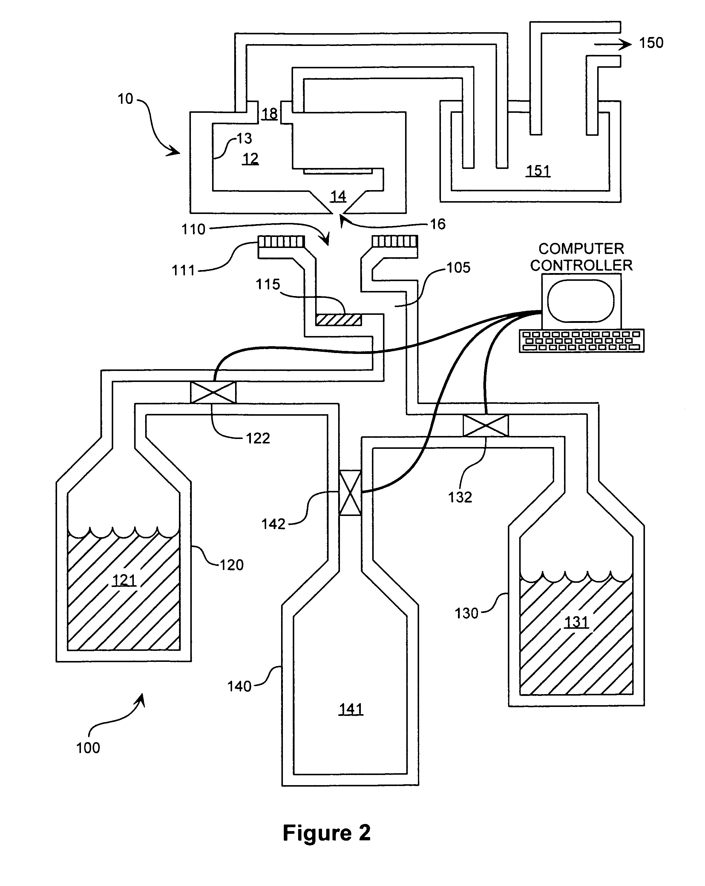
Method and apparatus to clean an inkjet reagent deposition device
a technology of inkjet reagent and deposition device, which is applied in the direction of printing, chemical/physical/physico-chemical processes, nucleotide libraries, etc., can solve the problems of compromising experimental integrity, reducing the capacity of producing arrays accurately and reliably, and in general inkjet printheads
- Summary
- Abstract
- Description
- Claims
- Application Information
AI Technical Summary
Benefits of technology
Problems solved by technology
Method used
Image


Examples
Embodiment Construction
[0028]Before describing the invention in detail, it must be noted that, as used in this specification and the appended claims, the singular forms “a,”“an,” and “the” include plural referents unless the context clearly dictates otherwise. Thus, for example, reference to “a fluid” includes more than one fluid, reference to “a solvent” includes a mixture of solvents and the like.
[0029]In describing and claiming the present invention, the following terminology will be used in accordance with the definitions set out below.
[0030]The terms “clean” and “cleaning” refer to removing particulate matter or other residue from the inner surfaces of an inkjet printhead, as by chemical or mechanical means.
[0031]The term “fluid” as used herein describes matter that is substantially liquid. Fluids may contain minimally, partially or fully solvated solids. Examples of fluids include, without limitation, deionized water, salt water, alcohols, other organic solvents, and the like.
[0032]The term “fluid c...
PUM
| Property | Measurement | Unit |
|---|---|---|
| volume percent | aaaaa | aaaaa |
| volume percent | aaaaa | aaaaa |
| time | aaaaa | aaaaa |
Abstract
Description
Claims
Application Information