Method and apparatus for monitoring and measuring oil spills

a technology for oil spills and methods, applied in direction finders, geological measurements, reradiation, etc., can solve the problems of large ecological problems, ineffective and expensive use of existing surveillance methods to achieve these goals, and inability to detect oil in marine environments. , to achieve the effect of increasing the output signal accuracy

Inactive Publication Date: 2006-03-07
MOELLER JENSEN PETER
View PDF15 Cites 35 Cited by
  • Summary
  • Abstract
  • Description
  • Claims
  • Application Information

AI Technical Summary

Benefits of technology

[0012]Another embodiment of the invention is directed to an oil spill detector for detecting oil spills from a ship-borne platform. The detector includes an oil spill sensor unit mountable to the ship-borne platform, the oil spill sensor unit having a microwave radiometer (MWR) sensor, at least one additional remote oil sensor. A data analyzer is coupled to receive ...

Problems solved by technology

Oil spills on a body of water present major ecological problems.
Ships and offshore installations are two of the biggest sources of this problem because the ships and installations dump more than 500,000 tons of oil into the marine environment every year.
However, these present strategies and the associated sporadic surveillance methods are proving inadequate to detect oil in marine environments.
However, using existing surveillance methods to achieve these goals is cost prohibitive, unreliable a...

Method used


Image

  • Method and apparatus for monitoring and measuring oil spills
  • Method and apparatus for monitoring and measuring oil spills
  • Method and apparatus for monitoring and measuring oil spills

Examples


Embodiment Construction

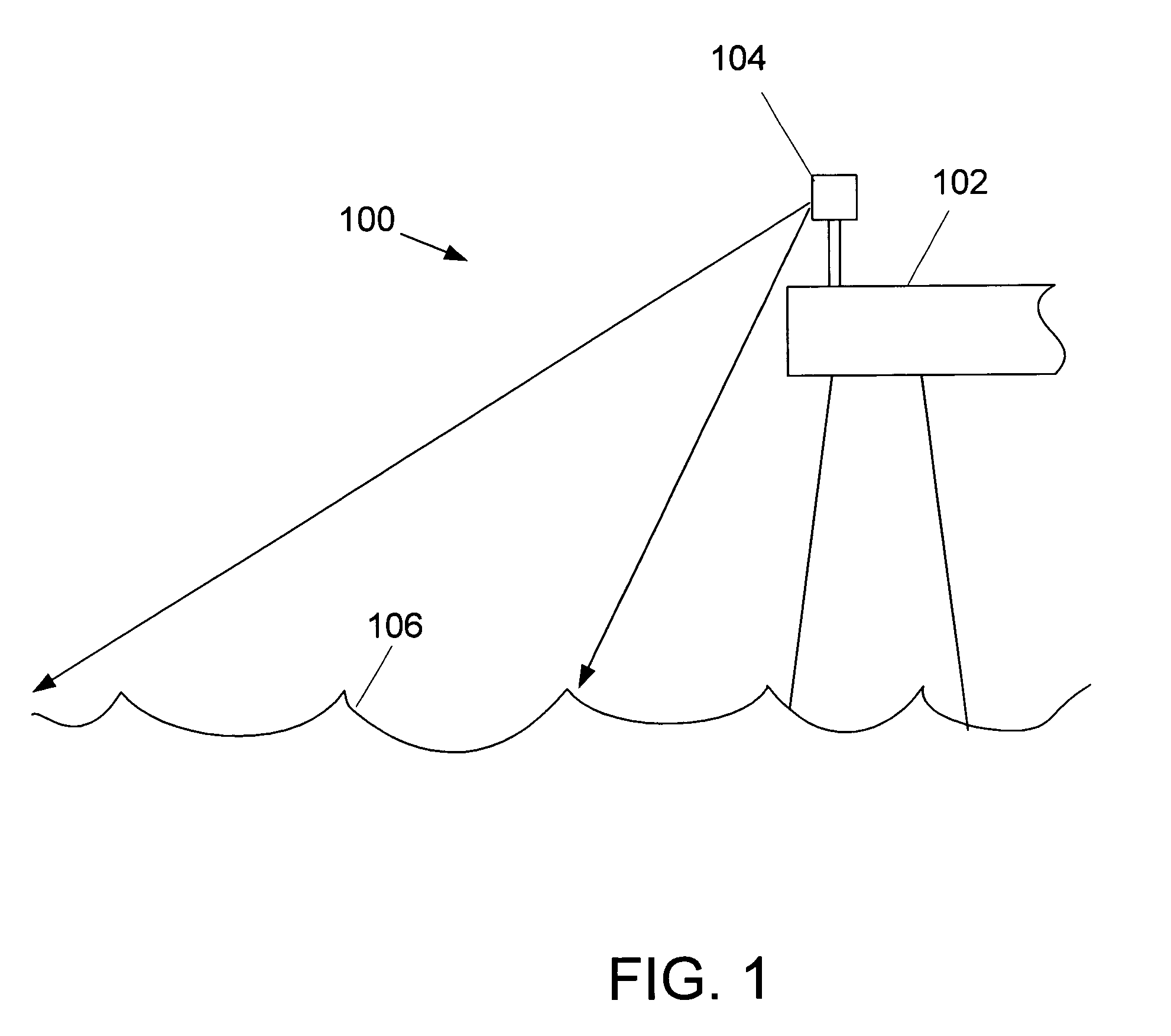
[0027]In general, the present invention is directed to a system for detecting and monitoring an oil spill that may be used for detecting oil spills on a lake, sea or ocean.

[0028]One particular embodiment of an oil spill identification system 100 according to the present invention is schematically illustrated in FIG. 1. A structure 102, for example an offshore structure such as an oil platform (as illustrated), or an onshore structure near the lake, sea or ocean shore is used for permanently mounting an oil spill sensor unit 104. The illustration shows only part of the structure 102. The sensor unit 104 is mounted on the structure 102 in such a way as to permit the monitoring of a large area of the water surface 106. Accordingly, onshore structures near the sea may include, but are not limited to, onshore-based wind turbines, lighthouses, funnels and / or tall building structures such as warehouses or silos in a harbor. The mounting of the oil spill sensor unit 104 on a fixed structure...


PUM


Abstract

The present invention relates to an oil spill identification system and oil spill identification sensors to be used in connection with this system. The system is used primarily on fixed offshore structures, but may also be used on fixed onshore constructions. The sensor comprises a combination of a radar and at least a microwave radiometer. The data collected are transmitted to a control station. Preferably, the transmittal takes place at pixel level between the sensors and the control station. The control station processes the data received at pixel level and transmits data to an end-user, preferably through the internet. The invention also relates to a method for utilizing the system and a use of the system.

Description

FIELD OF THE INVENTION[0001]The present invention relates in general to an oil-spill identification system and more particularly to a sensor package for monitoring and measuring petroleum products in a body of water.BACKGROUND[0002]Oil spills on a body of water present major ecological problems. Ships and offshore installations are two of the biggest sources of this problem because the ships and installations dump more than 500,000 tons of oil into the marine environment every year. To combat the problem, an increasing number of national, regional and international strategies have been and are being developed. However, these present strategies and the associated sporadic surveillance methods are proving inadequate to detect oil in marine environments.[0003]As a result, the Convention for the Protection of the Marine Environment of the Northeast Atlantic (the OSPAR Convention) is developing programs and measures for identifying emissions and discharges of substances. The goal of OSPA...

Claims


Application Information

Patent Timeline
IPC IPC(8): G01S13/95G01N33/18G01S7/41G01S13/88G01V11/00
CPCG01N33/1833G01V11/00G01S13/88G01S7/411Y02A20/20
Inventor MOELLER-JENSEN, PETER
Owner MOELLER JENSEN PETER
Why Eureka
Try Eureka