System and method for removing the relative phase uncertainty in device characterizations performed with a polarimeter

a technology of relative phase uncertainty and characterization method, which is applied in the field of high-speed communication systems, can solve the problems of polarimeter's inability to measure the individual, many optical devices have group delays, and many optical devices have polarization dependent group delays, so as to achieve rapid and accurate determination, rapid and accurate measurement of desired optical parameters, and the effect of prolonging the measuremen

Inactive Publication Date: 2006-03-07
AGILENT TECH INC
View PDF13 Cites 21 Cited by
  • Summary
  • Abstract
  • Description
  • Claims
  • Application Information

AI Technical Summary

Benefits of technology

[0006]In accordance with the invention, combining a typical polarimeter or polarization analyzer, such as the Agilent 8509B with an interferometer into a combined interferometric and polarimetric system allows the quick and accurate determination of the desired optical parameters such as: DGD, PMD, PDL, GD and CDassociated with a device under test (DUT) in a comparatively short period of time without repeated disconnecting and reconnecting of the DUT thereby satisfying the need for a rapid and accurate measurement of desired optical parameters. The DUT may be an inactive device such as an optical fiber or an active device such as an optical amplifier. In addition, the combined interferometric and polarimetric system in accordance with the invention allows an inexpensive way to extend the measurements that can be made using a polarization analyzer or polarimeter alone. Such a combined system is advantageous compared to present totally interferometric systems for determining the fast and slow group delays and the chromatic dispersion.

Problems solved by technology

Many optical devices have group delays that depend on the input polarization state.
Effectively, these optical devices have a polarization dependent group delay.
This limitation reflects the polarimeter's inability to measure the individual group delay of the fast polarization input state and of the slow polarization input state.
Unfortunately, the information provided by the Jones matrix is not sufficient to determine chromatic dispersion (CD) and group delay (GD) of the principal states of polarization.
However, a polarization analyzer can only measure the relative group delay, i.e. DGD, between the two principle states of polarization.
This measurement procedure requires two relatively expensive and complicated instruments to be used independently of each other for measurements on the device under test (DUT).
The DUT must be measured at separate times by two completely distinct measurement systems which may also introduce errors into the measurement process.

Method used


Image

  • System and method for removing the relative phase uncertainty in device characterizations performed with a polarimeter
  • System and method for removing the relative phase uncertainty in device characterizations performed with a polarimeter
  • System and method for removing the relative phase uncertainty in device characterizations performed with a polarimeter

Examples


Embodiment Construction

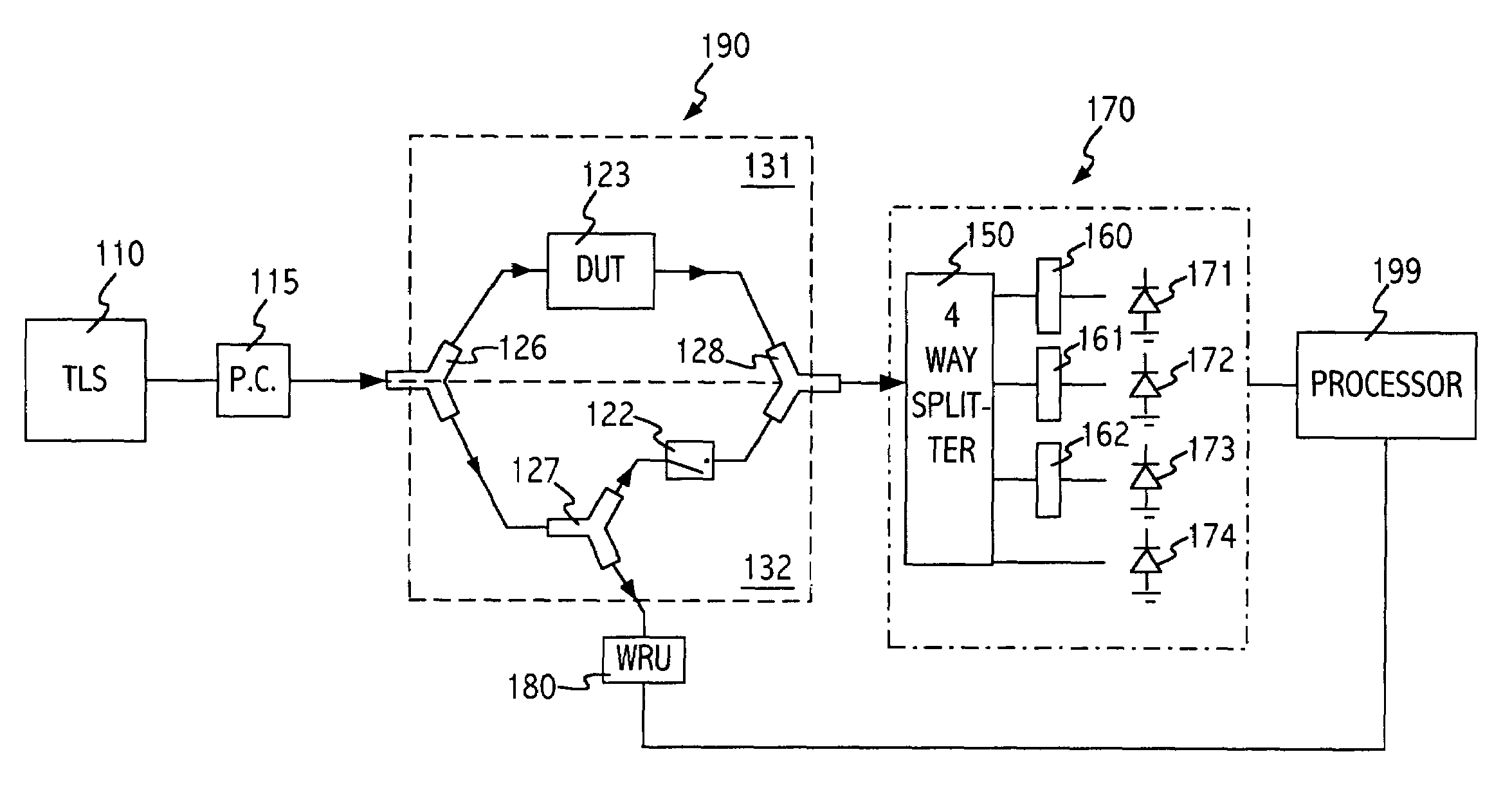
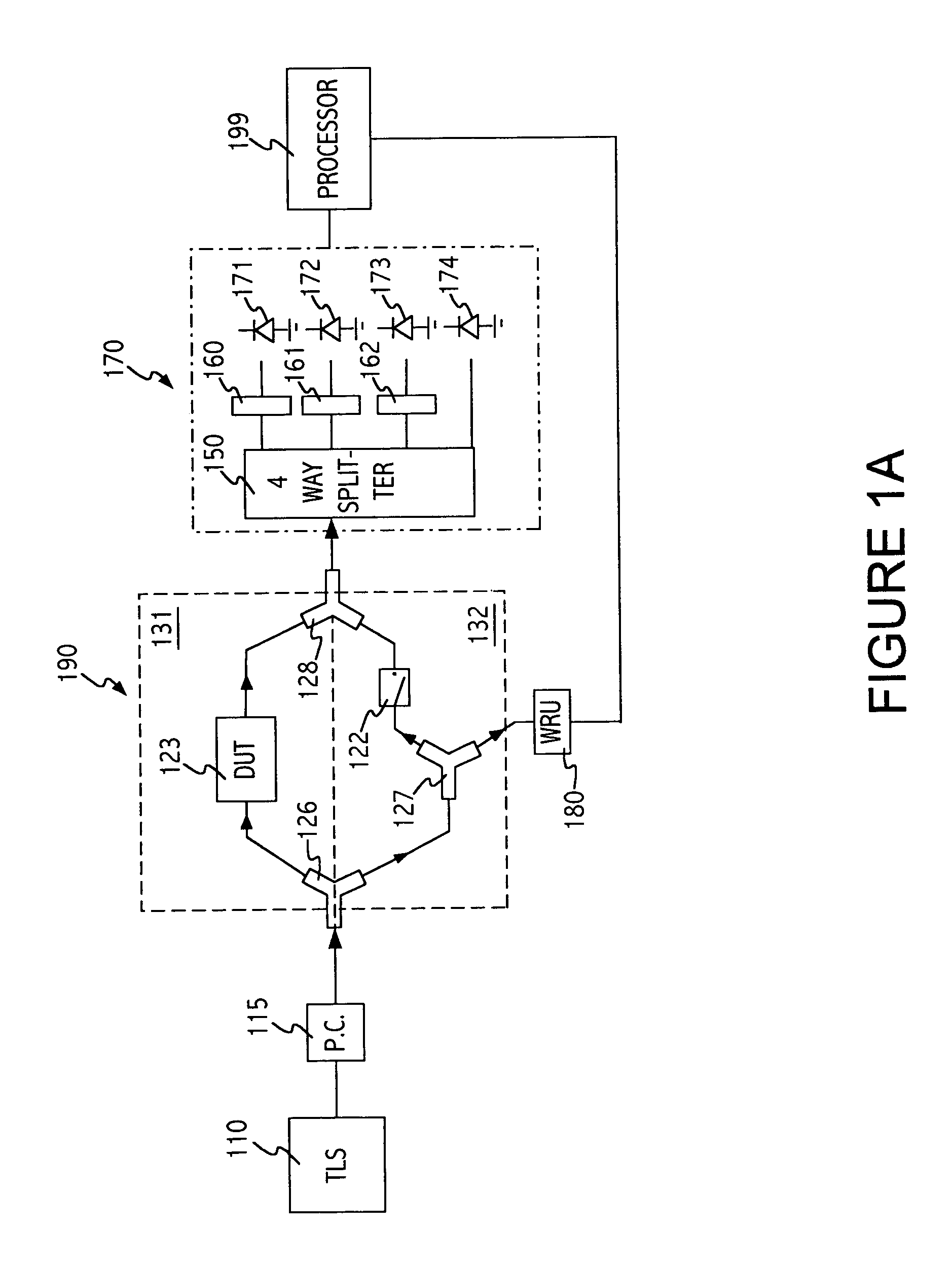
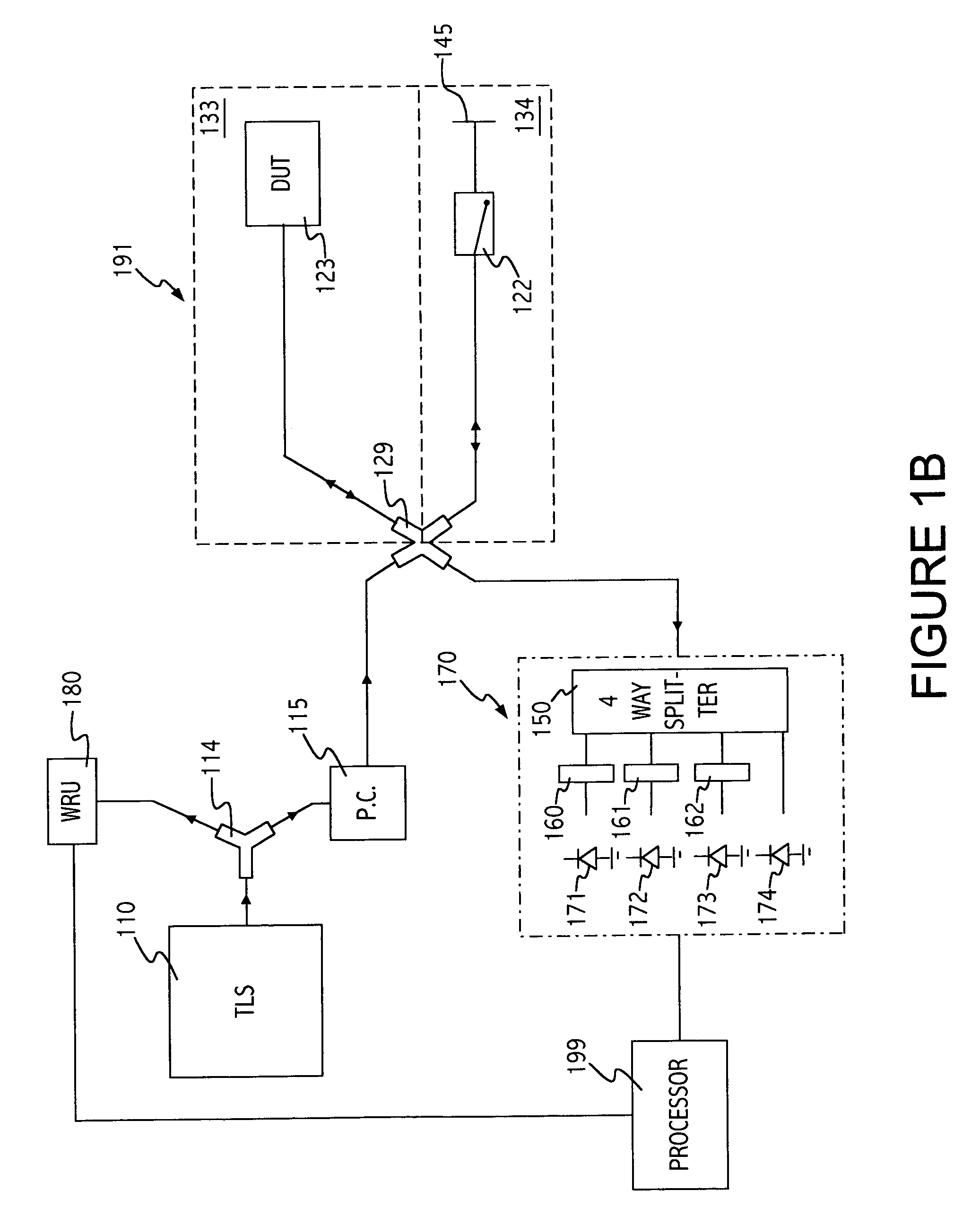
[0013]The Jones matrix, U of an optical device under test can be readily determined using a typical polarization analyzer. The Jones matrix, U is only determined to within a complex constant C, where C is a complex constant whose phase is the phase difference between the input and output light of the device under test and whose magnitude is related to the transmittance of the optical device under test. This complex constant cannot be determined using a typical polarimeter alone. The transfer matrix T is written as: T_=C⁢U_=C⁡(u11u12u21u22)(1)

The elements of the Jones matrix, uij, can be determined from polarimeter measurements but C cannot. The transfer matrix of a device under test (DUT) describes the relationship between the light input to the DUT and the light output from the DUT. Mathematically, this relationship may be expressed as

T{right arrow over (Ein)}=σeiφ{right arrow over (Eout)}  (2)

where {right arrow over (Ein)} and {right arrow over (Eout)} are unit vectors.

[0014]If {r...


PUM


Abstract

By making combined interferometric and polarimetric measurements on a device under test, the relative phase uncertainty in device characterizations performed with a polarimeter or polarization analyzer alone is removed. This allows determination of the group delay to within a constant offset and the chromatic dispersion of the device under test.

Description

BACKGROUND OF INVENTION[0001]Today's high speed communication systems require accurate knowledge of the group delay of a device as a function of wavelength. Many optical devices have group delays that depend on the input polarization state. Effectively, these optical devices have a polarization dependent group delay. Measurements performed with a polarimeter only enable the determination of the difference between the group delay of the fast polarization input state and the slow polarization input state. This limitation reflects the polarimeter's inability to measure the individual group delay of the fast polarization input state and of the slow polarization input state.[0002]Typical polarimeters are capable of determining the Jones matrix of an optical device. The information contained in the Jones matrix is sufficient to determine many transmission properties of a two-port optical device, such as the differential group delay (DGD), polarization mode dispersion (PMD) and the polariz...

Claims


Application Information

Patent Timeline
Patent Type & Authority Patents(United States)
IPC IPC(8): G01B9/02G01J3/447G01J4/04G01M11/00G01M11/02
CPCG01M11/31G01M11/338G01M11/331
Inventor VANWIGGEREN, GREGORY D.BANEY, DOUGLAS M.
Owner AGILENT TECH INC
Why Eureka
Try Eureka