Method and device for obtaining a sample with three-dimensional microscopy

a three-dimensional microscopy and sample technology, applied in the direction of fluorescence/phosphorescence, optical radiation measurement, instruments, etc., can solve the problems of preventing good acquisition of image, difficult to interpret images, and difficult to conventional fluorescence microscopy

Inactive Publication Date: 2006-03-07
UNIV LIBRE DE BRUXELIES
View PDF8 Cites 44 Cited by
  • Summary
  • Abstract
  • Description
  • Claims
  • Application Information

AI Technical Summary

Benefits of technology

[0023]The partially coherent light source may comprises a source (S) emitting light of small spectral width, a first lens (L1), a first aperture (A1), a second lens (L2), a second aperture (A2) and a third lens (L3), wherein a relative arrangement of these various elements being such that, during operation, the light emitted by the light-emitting source encounters, in succession, the first lens (L1), the first aperture (A1), the second lens (L2), the second aperture (A2) and the third lens (L3), and wherein the light at the exit of the third lens is collimated light. Alternatively, the partially coherent light source may comprise a source (S) emitting light of small spectral width, an optical fiber, a first lens (L1), a second lens (L2), a third lens (L3) and an adjustable aperture (A1), wherein a relative arrangement of these various elements being such that, during operation, the light emitted by the light-emitting source passes firstly through the optical fiber so as to have a homogeneous light field and then encounters the first lens (L1), then the second lens (L2) and the third lens (L3) in order to obtain collimated light at the aperture (A1). Alternatively, the p

Problems solved by technology

However, one of the problems encountered in conventional fluorescence microscopy is that of the fluorescence emitted by elements lying outside the plane of sharpness.
This parasitic light prevents good acquisition of the image by adding substantial background noise.
The images become very difficult to interpret when thick biological specimens, such as embryons, are observed.
However, confocal microscopy also has its own drawbacks.
One drawback of confocal microscopy is that this technique requires complete scanning of the specimen by an optomechanical device.
This operati

Method used


Image

  • Method and device for obtaining a sample with three-dimensional microscopy
  • Method and device for obtaining a sample with three-dimensional microscopy
  • Method and device for obtaining a sample with three-dimensional microscopy

Examples


Embodiment Construction

[0031]The following detailed description presents a description of certain specific embodiments of the present invention. However, the present invention may be embodied in a multitude of different ways as defined and covered by the claims. In this description, reference is made to the drawings wherein like parts are designated with like numerals throughout.

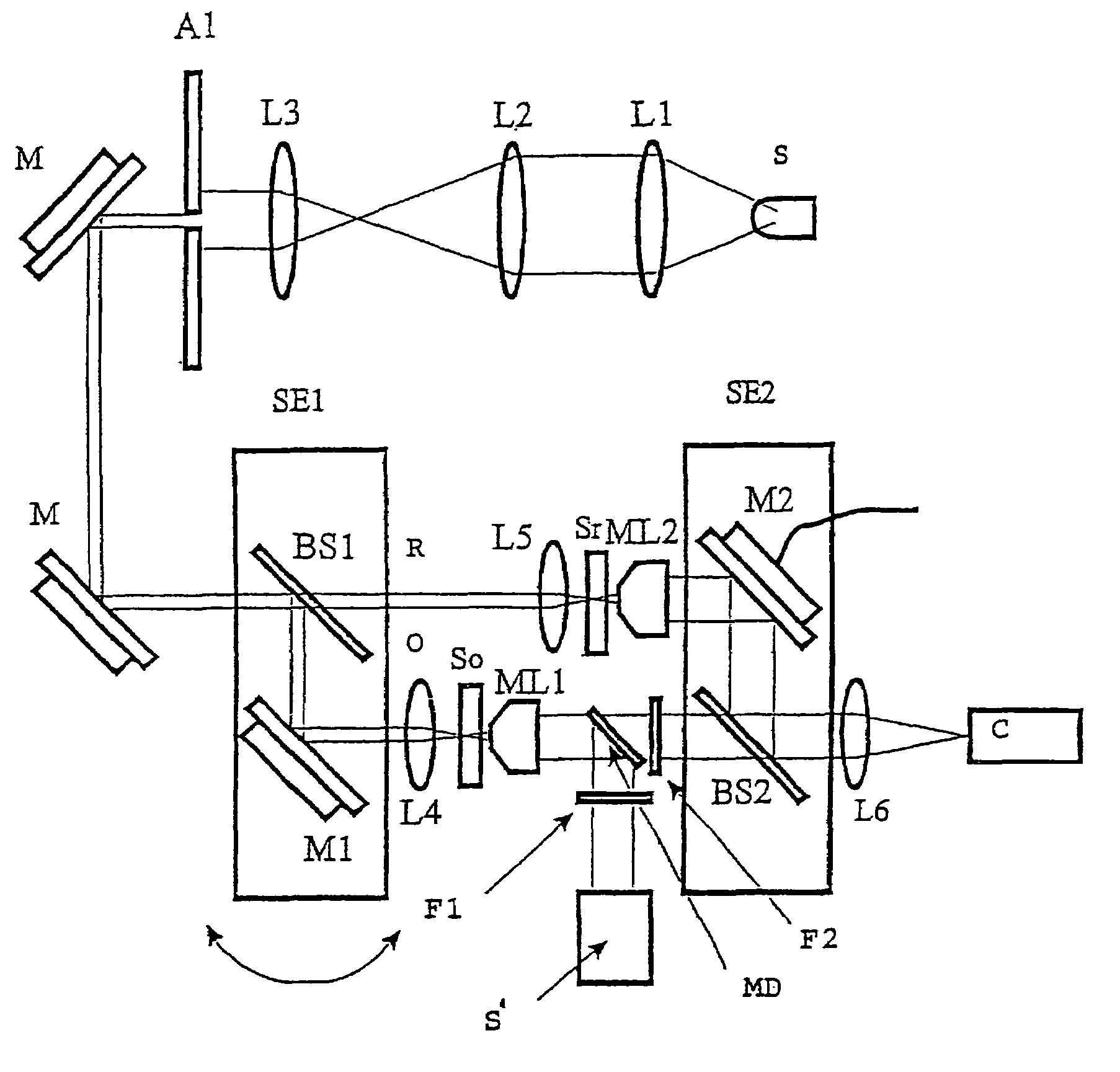
[0032]One embodiment of the present invention provides a method and an instrument that make it possible to obtain, by microscopy, three-dimensional images of a specimen, in particular a thick biological specimen, and to measure, in three dimensions, the fluorescence emitted thereby, and that do not have the drawbacks of the conventional microscopy techniques, including those of confocal microscopy.

[0033]In particular, another embodiment of the present invention provides a method and an instrument that make it possible both to obtain three-dimensional images of the specimen and of the fluorescence field of this specimen, that is to...


PUM


Abstract

A method and device for obtaining a sample with three-dimensional microscopy, in particular a thick biological sample and the fluorescence field emitted by the sample. One embodiment includes obtaining interferometric signals of a specimen, obtaining fluorescence signals emanating from the specimen, recording these signals, and processing these signals so as to reconstruct three-dimensional images of the specimen and of the field of fluorescence emitted by the specimen at a given time. Another embodiment includes a digital holography microscope, a fluorescence excitation source illuminating a specimen, where the microscope and the fluorescence excitation source cooperate to obtain interferometric signals of the specimen and obtain fluorescence signals emanating from the specimen, means for recording the interferometric signals and fluorescence signals, and means for processing the interferometric signals and the fluorescence signals so as to reconstruct three-dimensional images of the specimen and of the field of fluorescence emitted by the specimen at a given time.

Description

RELATED APPLICATIONS[0001]This application is a continuation application under 35 U.S.C. § 120 of WO 03 / 002972, filed as Patent Cooperation Treaty / BE02 / 00111 on Jul. 1, 2002, which is hereby incorporated by reference.BACKGROUND[0002]1. Field of the Invention[0003]Aspects of the present invention relate to a method and to an instrument for obtaining three-dimensional images of a specimen by microscopy and for obtaining, in three dimensions, the field of fluorescence emitted by this specimen, said specimen being either fluorescent or prelabeled using one or more fluorochromes.[0004]One of the applications of said method and of said instrument relates more particularly to obtaining three-dimensional images of the fluorescence emitted by biological specimens, that may be thick, for the purpose of observing their dynamic behavior and their change over time.[0005]2. Description of the Related Technology[0006]Conventional fluorescence microscopy has provided substantial progress in the fie...

Claims


Application Information

Patent Timeline
IPC IPC(8): G01J3/30G03H1/26G01N21/64G02B21/06G02B21/22G03H1/08
CPCG01N21/6458G02B21/16G02B21/365G03H1/0005G03H1/0866G03H1/041G03H2001/0456G03H2001/0458G03H2222/24G03H2223/26G03H2001/005G03H1/0443G03H1/0465G03H2001/0452G03H2223/14
Inventor DUBOIS, FRANKYOURASSOWSKI, CATHERINE
Owner UNIV LIBRE DE BRUXELIES
Why Eureka
Try Eureka