Broadband cascade light emitters

a cascade light and wideband technology, applied in the direction of semiconductor lasers, laser output parameters control, laser details, etc., can solve the problems of inefficient transition and difficulty in optimizing both

Active Publication Date: 2006-03-07
ALCATEL-LUCENT USA INC +1
View PDF11 Cites 6 Cited by
  • Summary
  • Abstract
  • Description
  • Claims
  • Application Information

AI Technical Summary

Benefits of technology

[0015]In accordance with one aspect of our invention, a broadband CLE capable of operation simultaneously at multiple wavelengths comprises: a core region including a multiplicity or cascade of stages, each stage including a radiative transition region. A first group of stages emits radiation at a first wavelength and at a first aggregate intensity per group, and a second group of stages emits radiation at a second wavelength and at a second aggregate intensity per group lower than the first intensity. The invention is characterized in that the second group has more stages than said first group, and the per-stage intensity of the first group is greater than that of the second group. This design reduces the difference between said first and second aggregate intensities. In one embodiment, groups that are located at or near to the ends of the cascade have more stages than groups that are centrally located within the cascade regardless of their wavelength.
[0016]Our invention significantly reduces variations in modal gain across the desired broadband spectrum and produces sufficiently flat gain without requiring elaborate redesign of the stages. These features have enabled us to achieve cw operation of a broadband ISB laser.

Problems solved by technology

However, the transitions were inefficient, and it was difficult to optimize both at the same time.
However, discrepancies between calculations and experiments were significant and caused considerable variation of the net modal gain across the spectrum that prevented broadband cw operation of these lasers.

Method used


Image

  • Broadband cascade light emitters
  • Broadband cascade light emitters
  • Broadband cascade light emitters

Examples


example

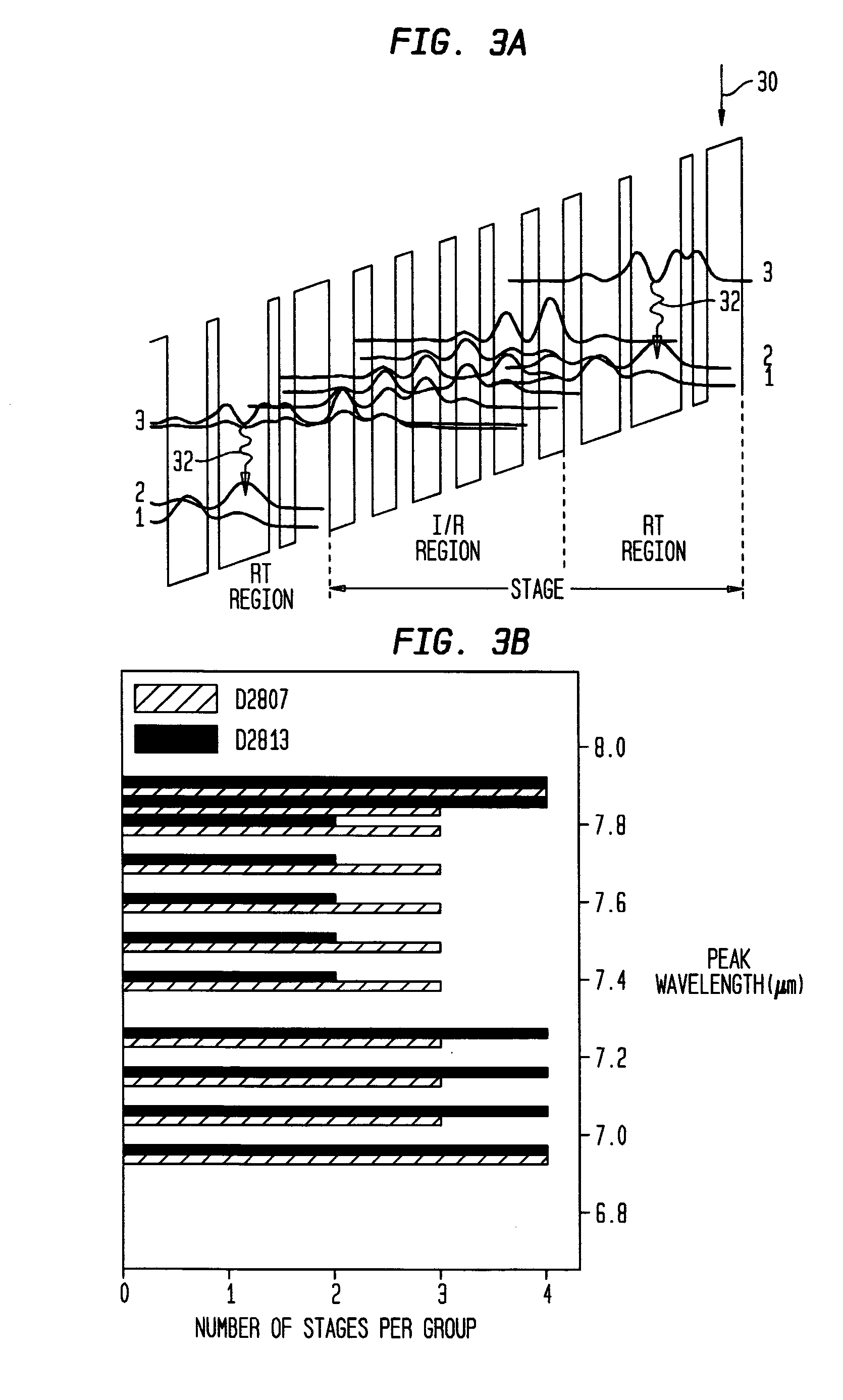
[0040]This example describes a Group III-V compound semiconductor, broadband ISB laser that was designed for operation at center wavelengths of 6.9 μm to 7.9 μm. Various materials, dimensions and operating conditions are provided by way of illustration only and, unless otherwise expressly stated, are not intended to limit the scope of the invention.

[0041]More specifically, the ISB laser of this example enabled us to achieve a small (about 4 cm−1) gain ripple across our target wavelength region and demonstrate the broadband cw operation of QC lasers. These lasers emitted simultaneously at many modes between 6.7 μm and 7.4 μm at temperatures ranging from 20 to 77 K.

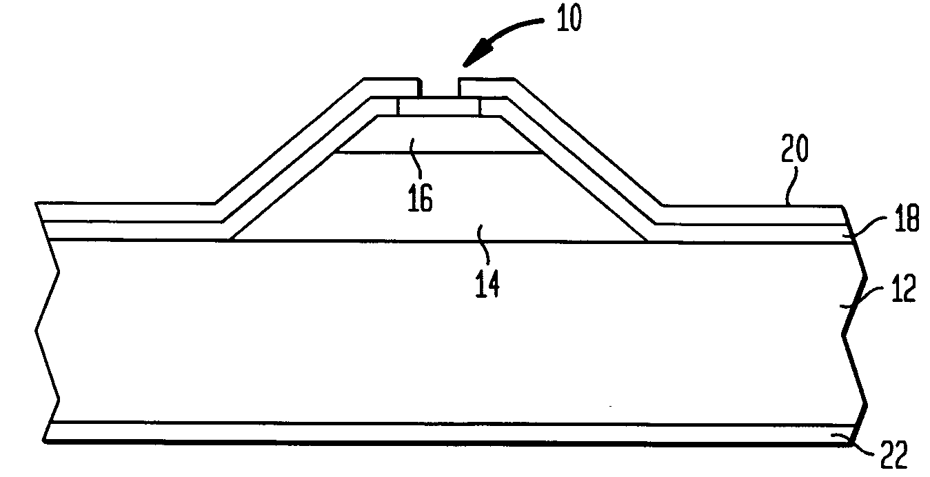
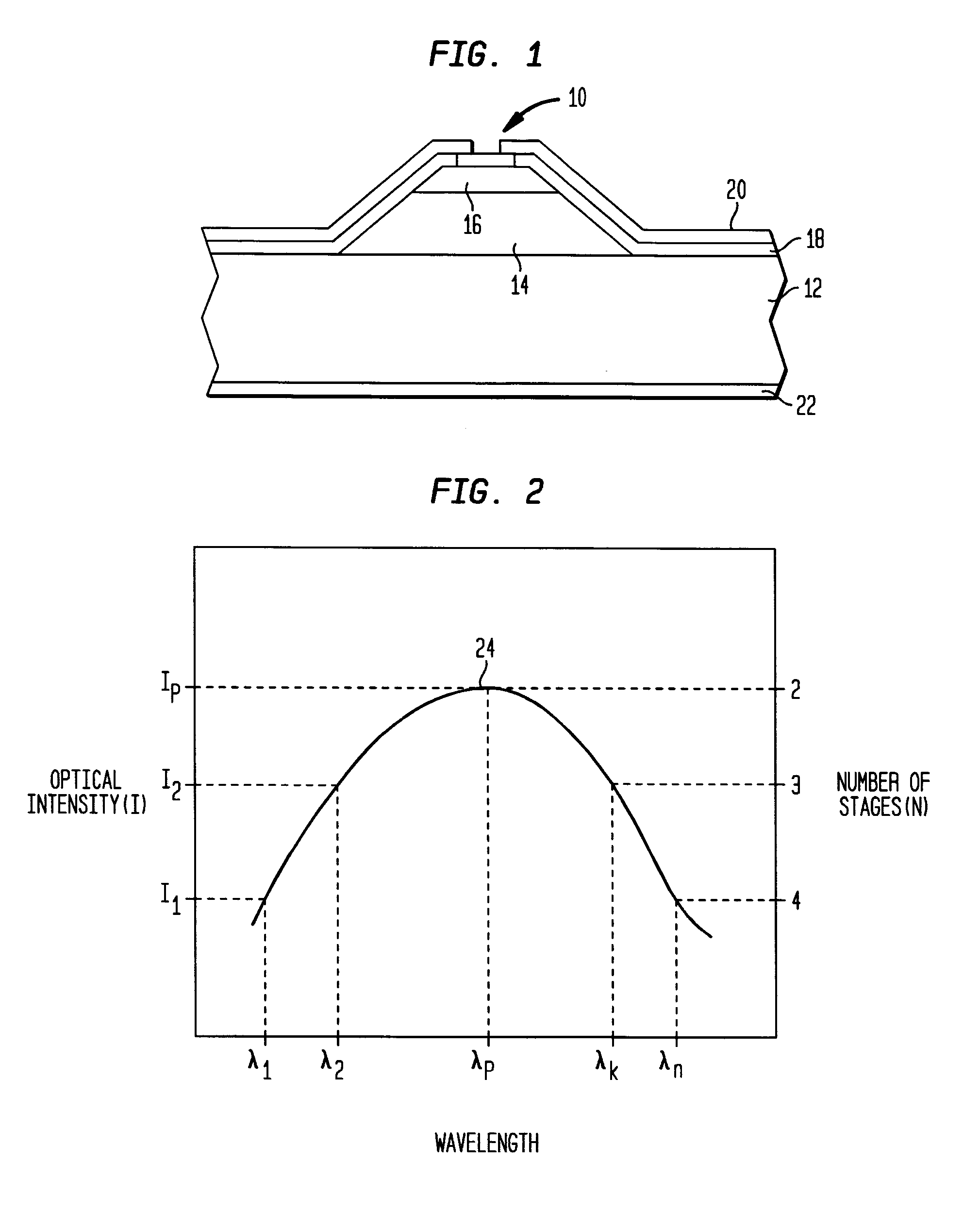
[0042]The lasers were grown by Molecular Beam Epitaxy (MBE) using In0.53Ga0.47As and Al0.48In0.52As lattice matched to an InP substrate. The bottom cladding region 12 was formed by the low n-type doped (n˜2×1017 cm−3) InP substrate. A 600 nm thick n-doped (3×1016 cm−3) InGaAs layer followed by 35 stages (I / R and RT regions)...


PUM


Abstract

A broadband CLE capable of operation simultaneously at multiple wavelengths comprises: a core region including a multiplicity or cascade of stages, each stage including a radiative transition region. A first group of stages emits radiation at a first wavelength and at a first aggregate intensity per group, and a second group of stages emits radiation at a second wavelength and at a second aggregate intensity per group lower than the first intensity. The invention is characterized in that the second group has more stages than said first group, and the per-stage intensity of the first group is greater than that of the second group. This design reduces the difference between said first and second aggregate intensities. In one embodiment, groups that are located at or near to the ends of the cascade have more stages than groups that are centrally located within the cascade regardless of their wavelength. Our invention significantly reduces variations in modal gain across the desired broadband spectrum and produces sufficiently flat gain without requiring elaborate redesign of the stages. These features enable cw operation of a broadband intersubband laser.

Description

GOVERNMENT CONTRACT[0001]This invention was made with Government support under Contract No. DAAD19-00-C-0096 by the DARPA / US Army Research Office. The Government has certain rights in this invention.BACKGROUND OF THE INVENTION[0002]1. Field of the Invention[0003]This invention relates to semiconductor cascade light emitters (CLEs) in general and, more particularly, to broadband intersubband (ISB) [e.g., quantum cascade (QC)] lasers adapted for continuous wave (cw) operation.[0004]2. Discussion of the Related Art[0005]A broadband emitter has two principal characteristics: first, it simultaneously emits optical radiation (light) at multiple wavelengths, and second, adjacent emission wavelengths are sufficiently close to one another that their intensity does not fall to zero in the spectral region between them. The latter characteristic also means that the tails of the intensity profiles of adjacent wavelengths overlap one another. Broadband CLE devices include ISB cascade emitters, wh...

Claims


Application Information

Patent Timeline
Patent Type & Authority Patents(United States)
IPC IPC(8): H01S5/00
CPCB82Y20/00H01S5/06H01S5/22H01S5/1096H01S2304/02H01S5/3422H01S5/34306H01S5/34313H01S5/2214
Inventor CAPASSO, FEDERICOCHO, ALFRED YIGMACHL, CLAIRE F.PEABODY, MILTON L.SERGENT, ARTHUR MIKESIVCO, DEBORAH LEESOIBEL, ALEXANDER
Owner ALCATEL-LUCENT USA INC
Why Eureka
Try Eureka