Variable field of view optical system

a technology of optical systems and variable fields, applied in the field of variable field of view optical systems, can solve the problems of limiting the size of manmade imagers, limiting the capability of imaging systems, and preventing manmade systems from completely duplicating

Inactive Publication Date: 2006-03-07
LOCKHEED MARTIN CORP
View PDF6 Cites 7 Cited by
  • Summary
  • Abstract
  • Description
  • Claims
  • Application Information

AI Technical Summary

Benefits of technology

[0011]The present invention is of a variable field of view optical system and method comprising: providing a forward curved optical element; providing a rearward optical element comprising an axially gradient index material; providing a curved focal surface; and conveying an image on the curved focal surface to a flat detector surface. In the preferred embodiment, the forward curved optical element comprises a ball lens. Conveying may comprise employing a backward curving or hollow field relay lens. Conveying may also comprise employing a plurality of optical fibers, preferably wherein the fibers are concentrated more densely in a center of the focal surface than in a periphery of the focal surface and wherein the fibers are mounted normal to the curved focal surface. The rearward optical element comprises a dynamic index material, preferably an electroactive hydrogel. The method provides simultaneous wide field of view with a lower resolution and narrow field of view with higher resolution, and employs substantially no moving parts.

Problems solved by technology

A host of issues prevent manmade systems from completely duplicating the biological approach.
This also limits the size of a manmade imager, since optical devices, even manmade, work best with spherical focal planes, and must be compensated for flat focal planes.
For example, every defense system that requires optical imaging is limited by the capability of the imaging system.

Method used


Image

  • Variable field of view optical system
  • Variable field of view optical system
  • Variable field of view optical system

Examples


Embodiment Construction

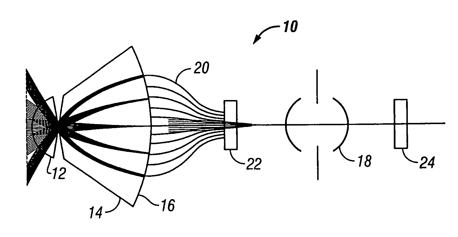
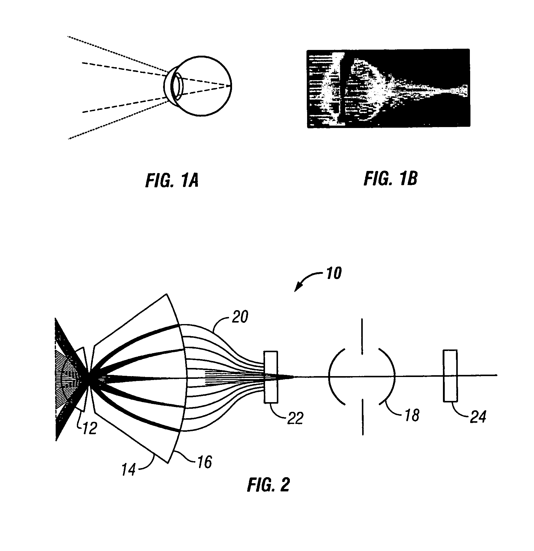
[0018]In the human eye the cornea and the lens form the imaging mechanism and are responsible for focusing a clear image onto the retina. The two lenses are both fixed in position. To focus an image on the retina, the interior lens remains stationary, but changes shape. Octopus eyes are similar to those of humans in that each has a lens, iris, pupil, and retina, but no cornea. FIG. 1 outlines the anatomy of the human and octopus eyes. The octopus relies primarily on its vision to survive, with its stereoscopic binocular vision both forward and above, providing an almost 2π steradian field of view. The octopus changes the position of its lens relative to the retina in order to keep both near and far objects in sharp focus at all times—a definite advantage for an animal that must be constantly searching for nearby food, but still keep an eye on the horizon for possible predators. The present invention mimics this focusing mechanism by dynamically altering the refractive index of the o...


PUM


Abstract

A variable field of view optical system and method comprising providing a forward curved optical element, providing a rearward optical element comprising an axially gradient index material, providing a curved focal surface, and conveying an image on the curved focal surface to a flat detector surface.

Description

CROSS-REFERENCE TO RELATED APPLICATIONS[0001]Not Applicable.STATEMENT REGARDING FEDERALLY SPONSORED RESEARCH OR DEVELOPMENT[0002]Not Applicable.INCORPORATION BY REFERENCE OF MATERIAL SUBMITTED ON A COMPACT DISC[0003]Not Applicable.COPYRIGHTED MATERIAL[0004]Not Applicable.BACKGROUND OF THE INVENTION[0005]1. Field of the Invention (Technical Field)[0006]The present invention relates to methods and apparatuses for variable field of view optical systems.[0007]2. Description of Related Art[0008]In imaging applications, a wide view of the surroundings (with low resolution) is needed to find areas of interest, while a narrow field of view with high resolution is required to investigate the details of these high-interest areas. Advanced biological imaging systems resolve this dilemma with a high-resolution central area and a lower resolution periphery. The high-resolution area is optimized for accurate imaging, and controls the intensity and focus of the overall system. The periphery is opt...

Claims


Application Information

Patent Timeline
Patent Type & Authority Patents(United States)
IPC IPC(8): G02B6/42G02B3/00
CPCG02B13/22G02B13/18G02B13/12G02B6/06
Inventor GRAHAM, AMY G.AMON, MAXLEBLANC, RICHARD A.
Owner LOCKHEED MARTIN CORP
Why Eureka
Try Eureka