Supercharge Your Innovation With Domain-Expert AI Agents!

Pre-equalizer structure based on PN511 sequence for terrestrial DTV reception

a pre-equalizer and terrestrial dtv technology, applied in the field of signal processing for wireless receivers, can solve the problems of poor performance, inability to facilitate carrier recovery or timing recovery, and failure of advanced television system committee (atsc) digital television terrestrial receivers, etc., to improve signal quality and increase the probability of successful decoding

Inactive Publication Date: 2006-03-07
KONINKLIJKE PHILIPS ELECTRONICS NV
View PDF13 Cites 8 Cited by
  • Summary
  • Abstract
  • Description
  • Claims
  • Application Information

AI Technical Summary

Benefits of technology

[0005]To address the above-discussed deficiencies of the prior art, it is a primary object of the present invention to provide, for use in a wireless receiver, a free-running sample rate converter and a large spanning, non-linear pre-equalizer which are employed before a timing recovery loop within a wireless receiver chain, while retaining equalization after the timing recovery loop (at the input of a sync detector). A channel identifier produces a channel estimate from the PN511 training sequence within the received wireless signals, with the pre-equalizer employing the resulting channel estimate to equalize the received signals being passed to the timing recovery loop, improving the signal quality for carrier and timing recovery and decoding to increase the probability of successful decoding while enabling the use of fast tracking forward and feedback equalizers for decoding.

Problems solved by technology

Current Advanced Television Systems Committee (ATSC) digital television (DTV) terrestrial receivers may fail due to the lack of clock recovery as a result of imperfections in the channel.
Moreover, occasionally an equalizer within such a receiver will not adapt to an optimum setting, causing poor performance.
However, equalizer 400 only performs equalization close in to the main signal due to the size limitations of the equalizer, and does not facilitate carrier recovery or timing recovery.

Method used


Image

  • Pre-equalizer structure based on PN511 sequence for terrestrial DTV reception
  • Pre-equalizer structure based on PN511 sequence for terrestrial DTV reception
  • Pre-equalizer structure based on PN511 sequence for terrestrial DTV reception

Examples


Embodiment Construction

[0013]FIGS. 1 through 3, discussed below, and the various embodiment used to describe the principles of the present invention in this patent document are by way of illustration only and should not be construed in any way to limit the scope of the invention. Those skilled in the art will understand that the principles of the present invention may be implemented in any suitably arranged device.

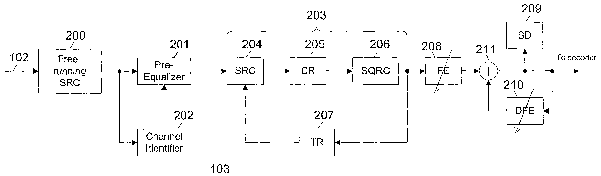
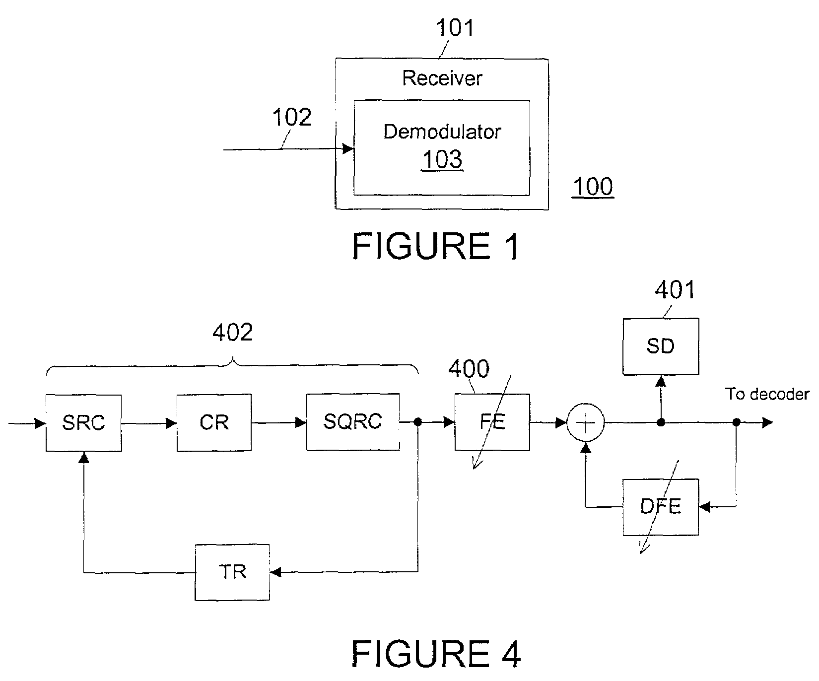
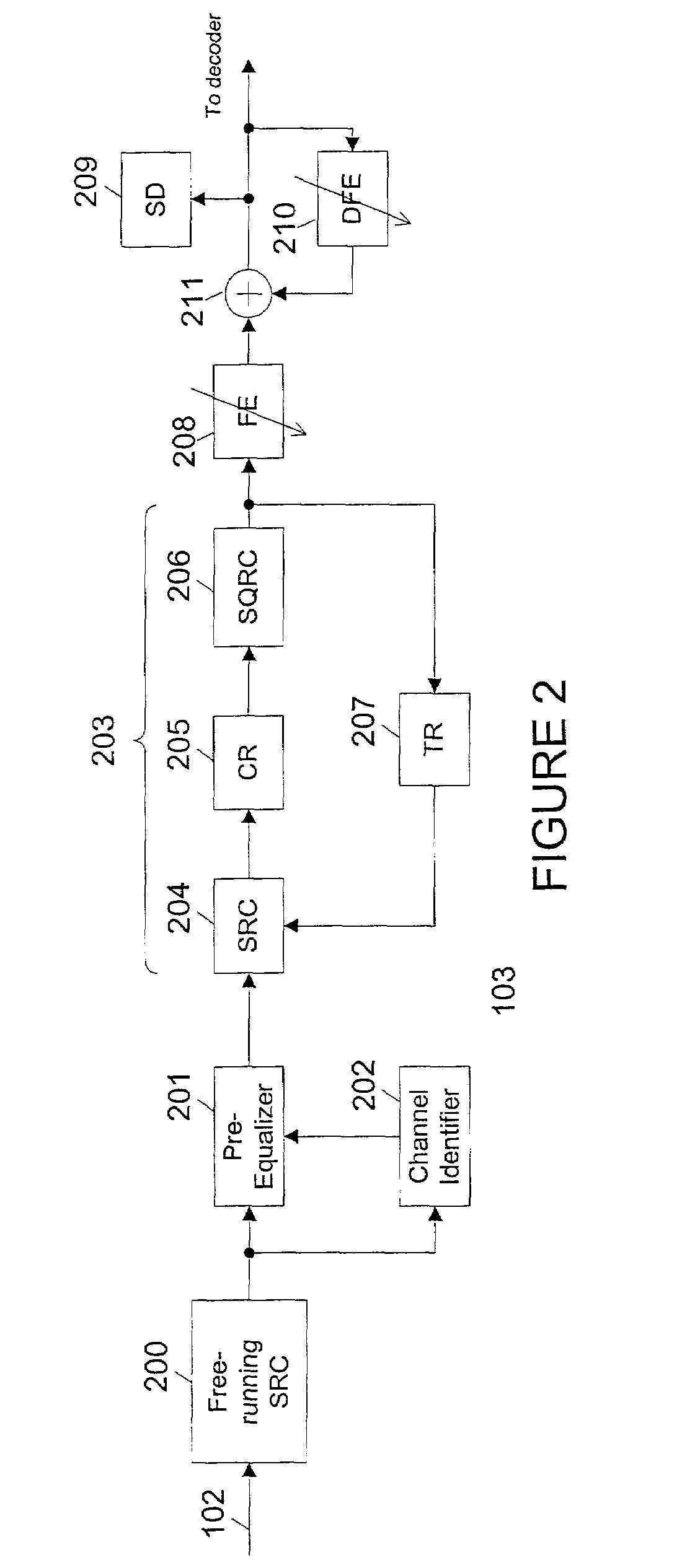
[0014]FIG. 1 depicts a receiver system including a pre-equalizer for improved channel equalization according to one embodiment of the present invention. Receiver system 100 includes a receiver 101, which is a digital television (DTV) receiver in the exemplary embodiment, including an input 102 for receiving wireless signals and a demodulator 103 including a pre-equalizer as described in greater detail below.

[0015]The present invention may also be employed for any receiver such as, for example, a broadband wireless Internet access receiver. Regardless of the embodiment, however, receiver 101 incl...


PUM


Abstract

A free-running sample rate converter and a large spanning, non-linear pre-equalizer are employed before a timing recovery loop within a wireless receiver chain, while forward and feedback equalization after the timing recovery loop (at and around the input of a sync detector) is also retained. A channel identifier produces a channel estimate from the PN511 training sequence within the received wireless signals, with the pre-equalizer employing the resulting channel estimate to equalize the received signals being passed to the timing recovery loop, improving the signal quality for carrier and timing recovery and decoding to increase the probability of successful decoding while enabling the use of fast tracking forward and feedback equalizers for decoding.

Description

TECHNICAL FIELD OF THE INVENTION[0001]The present invention is directed, in general, to signal processing for wireless receivers and, more specifically, to channel equalization within wireless receivers.BACKGROUND OF THE INVENTION[0002]Current Advanced Television Systems Committee (ATSC) digital television (DTV) terrestrial receivers may fail due to the lack of clock recovery as a result of imperfections in the channel. Moreover, occasionally an equalizer within such a receiver will not adapt to an optimum setting, causing poor performance.[0003]A typical ATSC wireless receiver implementation, illustrated in FIG. 4, places a small, semi-complex forward equalizer (FE) 400 in front of a sync detector (SD) 401, after the timing recovery loop 402, to improve synchronization lock. However, equalizer 400 only performs equalization close in to the main signal due to the size limitations of the equalizer, and does not facilitate carrier recovery or timing recovery.[0004]There is, therefore,...

Claims


Application Information

Patent Timeline
IPC IPC(8): H04B1/68H04L27/06H04L7/04H04L25/03
CPCH04L25/03146H04L7/041H04L2025/0377H04L2025/0349
Inventor MEEHAN, JOSEPH PATRICKKOO, DAVID
Owner KONINKLIJKE PHILIPS ELECTRONICS NV
Features
  • R&D
  • Intellectual Property
  • Life Sciences
  • Materials
  • Tech Scout
  • Unparalleled Data Quality
  • Higher Quality Content
  • 60% Fewer Hallucinations
Learn More