Method of manufacturing stator core of vehicle rotary electric machine

a technology of stator core and rotary electric machine, which is applied in the direction of magnetic body, magnetic circuit rotating parts, magnetic circuit shape/form/construction, etc., can solve the problems of increasing and preventing the magnetic resistance of teeth from increasing. , the effect of reducing the manpower for manufacturing the magnetic strip

Inactive Publication Date: 2006-03-14
DENSO CORP
View PDF19 Cites 11 Cited by
  • Summary
  • Abstract
  • Description
  • Claims
  • Application Information

AI Technical Summary

Benefits of technology

[0019]According to the above structure, the cross-section of the teeth at the middle thereof is not narrower than the cross-section at the base thereof. This shape prevents the magnetic reluctance thereof from increasing. In addition, it is possible to manufacture a plurality of magnetic strips from a long magnetic sheet.
[0020]As a result, the yield percentage of the magnetic strip can be improved and the manpower for manufacturing the magnetic strip can be reduced. In addition, the magnetic strip can be wound easily because of the notches.
[0021]According to another feature of the invention, the notch and projection are complementary to each other in shape before the magnetic strip is spirally wound, and the radial width of the notch is reduced after the strip is wound. Therefore, the yield percentage of the magnetic strip is drastically improved. Because the radial width of the notch is automatically reduced when the magnetic strip is wound, the magnetic reluctance from the teeth to the core back can be reduced.
[0022]According to another feature of the invention, the slot has parallel walls facing each other in circumferential directions. Therefore, it is easy to align the conductors in the slots, resulting in improvement of the space factor.
[0023]According to another feature of the invention, the magnetic strip is thicker than 0.2 mm and thinner than 0.5 mm. This thickness makes it possible to form the magnetic strips with small marginal portions and to stamp out two magnetic strips at once at a reduced cost and prevents the tooth edge from deforming.

Problems solved by technology

If the teeth of one of the pair of magnetic strips are respectively formed from portions inside slots of the other magnetic strip as disclosed in JP-A-299136, it is not possible to provide such a circumferentially wide tooth.
However, if the tooth is narrowed at the middle, the magnetic reluctance of the teeth increases, and the magnetic flux flowing through the stator core decreases significantly.
This lowers the output power.
However, if the thickness is reduced to a thickness less than 0.2 mm, the edge of the sheet may be drawn because of the low rigidity thereof.
As a result, the projections of the tooth edge can not have proper length, and a sufficient cross-section of the magnetic flux from the rotor can not be provided.

Method used


Image

  • Method of manufacturing stator core of vehicle rotary electric machine
  • Method of manufacturing stator core of vehicle rotary electric machine
  • Method of manufacturing stator core of vehicle rotary electric machine

Examples


first embodiment

[0037]A stator core of a vehicle AC generator according to the invention is described with reference to FIGS. 1–5.

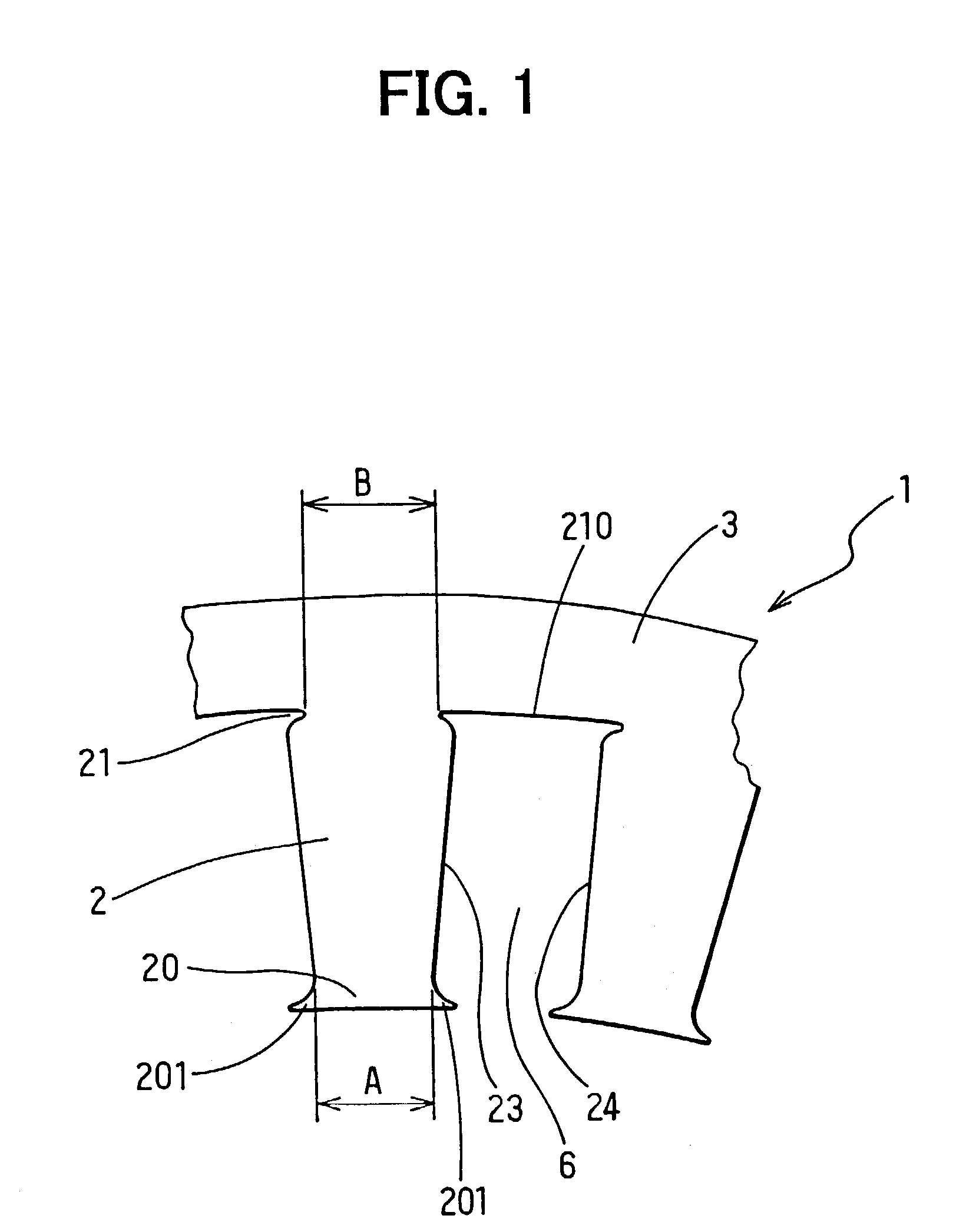
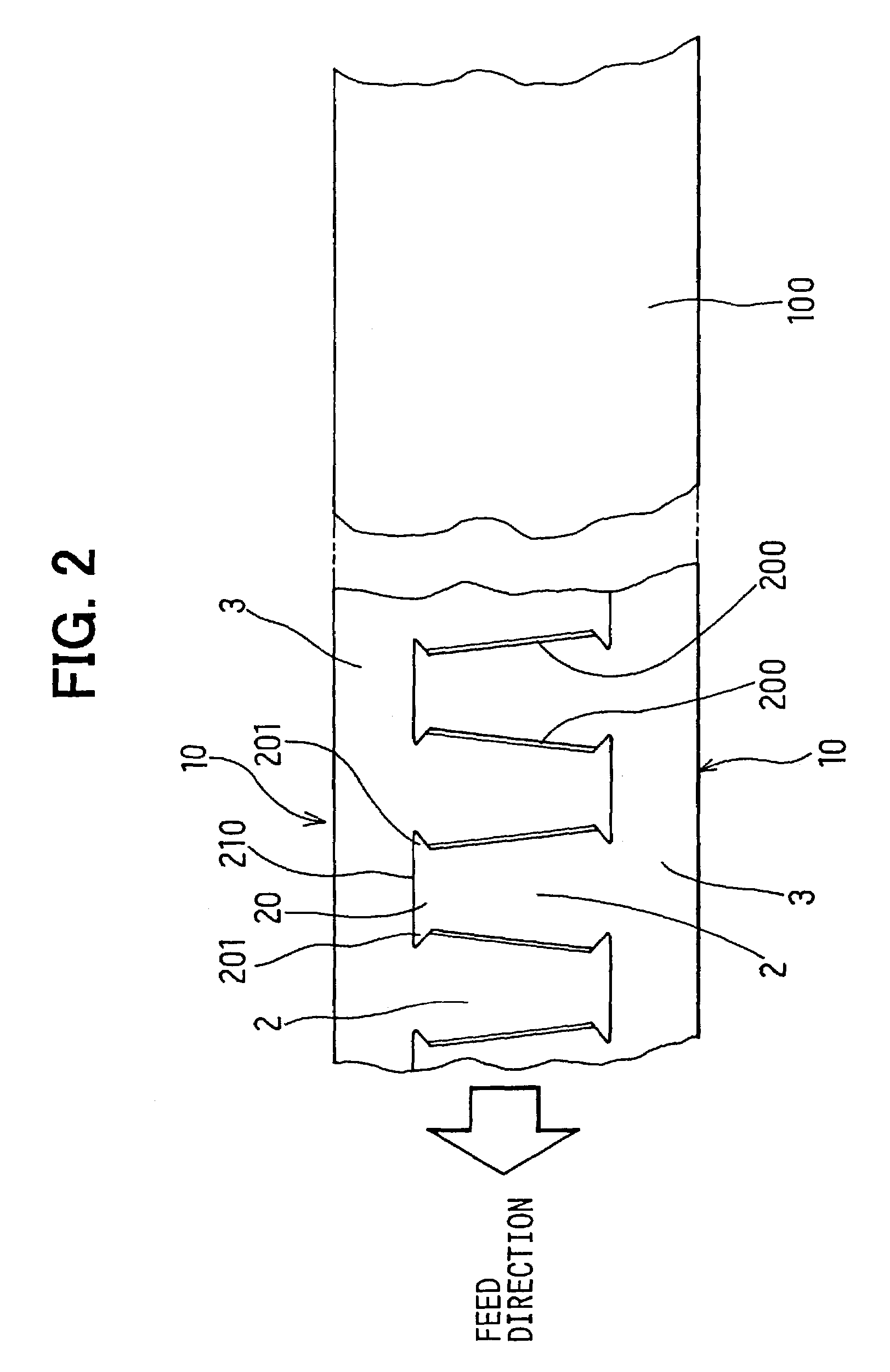
[0038]A cylindrical stator core 1 is comprised of a spirally wound and laminated magnetic strip 10 that is as thick as 0.35 mm. The magnetic strip 10 has a plurality of teeth 2 and a core back 3 from which the plurality of teeth 2 extends. When wound and laminated, tooth edges 20 of teeth 2 are disposed radially inside, as shown in FIG. 3.

[0039]A plurality of conductor coils 5 is disposed in each slot 6 formed between a pair of adjacent teeth 2, as shown in FIG. 5, so that an electromotive force can be generated in the conductor coils 5 when a rotor having a field coil (not shown) supplies an alternating magnetic flux. A pair of circumferential notches 21 is formed at opposite sides of a base portion of each tooth 2 adjacent to the core back 3. A width B of the base between the notches 21 is set larger than a minimum width A between a pair of circumferential projections ...

second embodiment

[0044]As a method of manufacturing the stator core according to the invention, a pair of magnetic strips that is overlapped each other can be stamped as shown in FIG. 7. This step reduces time of manufacturing magnetic strips 10. It is also possible to stamp out three overlapping magnetic strips at one time. Because the thickness of the magnetic strip 10 is comparatively small, the iron loss of the stator core can be reduced to increase the output power.

third embodiment

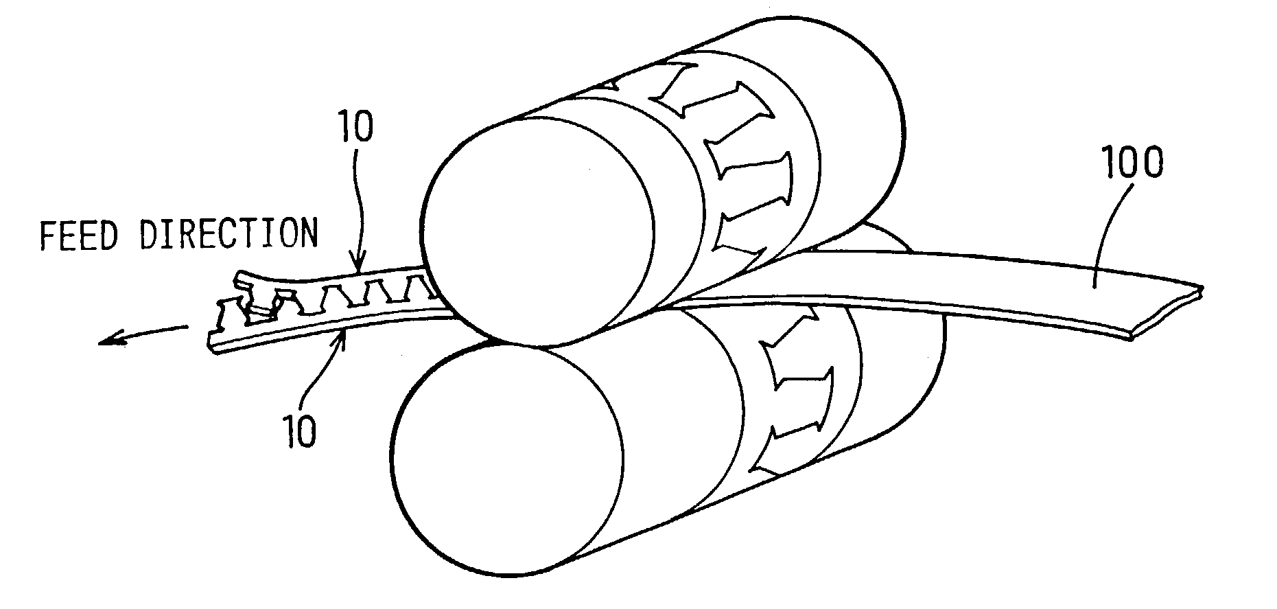
[0045]As a method of manufacturing the stator core according to the invention, a long magnetic sheet can be loaded between a pair of parallel rollers having a punch and a die to stamp out the magnetic strip 10 continuously, as shown in FIG. 8. Because the magnetic strip 10 can be formed continuously, the production time and cost can be reduced.

[0046]The thickness of the magnetic sheets can be changed from 0.35 mm to a thickness between 0.2 mm and 0.5 mm.

[0047]A stator core according to a fourth embodiment of the invention is described with reference to FIG. 9. A unit of the conductor coils 5 can be divided into two groups, and each output power is added to each other. The number of the slots per each unit length of the magnetic sheet becomes twice as many as the number of the slots of the magnetic sheet according to the first embodiment. On the other hand the width of the slots becomes a half the width of the slot of the magnetic sheet according to the first embodiment. Thus, the nu...


PUM

PropertyMeasurementUnit
thicknessaaaaaaaaaa
thicknessaaaaaaaaaa
diameteraaaaaaaaaa

Abstract

Each tooth of a stator core has circumferential projections at an inner tooth edge and circumferential notches at a base portion adjacent to a core back. A width of the teeth at the base portion is larger than a width of the same at the tooth edge. Therefore, the magnetic reluctance of the teeth does not increase. In addition, a plurality of the magnetic strips can be formed from a long and thin magnetic sheet. This increases the yield percentage of the magnetic strip and reduces a manpower of manufacturing the magnetic strip. Further, the notches make it easy to wind the magnetic strip into a cylindrical core.

Description

CROSS REFERENCE TO RELATED APPLICATION[0001]This is a division of application Ser. No. 09 / 827,213 filed on Apr. 6, 2001. The entire disclosure of the prior application is hereby incorporated by reference in its entirety.[0002]The present application is based on and claims priority from Japanese Patent Applications: 2000-113966, filed April 14 and 2000-359639, filed Nov. 27, 2000; the contents of which are incorporated herein by reference.BACKGROUND OF THE INVENTION[0003]1. Field of the Invention[0004]The present invention relates to a stator core of a vehicle rotary electric machine, such as an AC generator, to be mounted in a passenger car, a truck, etc.[0005]2. Description of the Related Art[0006]In order to supply an inexpensive vehicle rotary machine, a magnetic stator core is usually comprised of a spirally wound magnetic strip. Such a stator core can provide a high yield percentage magnetic material and can be manufactured at a high manufacturing speed.[0007]In order to meet a...

Claims


Application Information

Patent Timeline
Patent Type & Authority Patents(United States)
IPC IPC(8): H02K15/00H02K15/14H02K15/16H02K1/02H02K1/16H02K1/18H02K3/12H02K3/34H02K15/02
CPCH02K1/16H02K15/024H02K15/026H02K1/165Y10T29/49012Y10T29/49073Y10T29/49071Y10T29/49009
Inventor NAKAMURA, SHIGENOBU
Owner DENSO CORP
Why Eureka
Try Eureka