Embedded-sensor multi-hole probes

a multi-hole, embedded technology, applied in the direction of instruments, volume metering, liquid/fluent solid measurement, etc., can solve the problems of lack of flexibility, impracticality of techniques, and current state-of-the-art of such probes

Inactive Publication Date: 2006-03-14
AEROPROBE CORP
View PDF7 Cites 17 Cited by
  • Summary
  • Abstract
  • Description
  • Claims
  • Application Information

AI Technical Summary

Benefits of technology

[0014]Accordingly it is an object of this invention to provide an improved high-performance, fast-response, multi-sensor pressure probe, and
[0016]It is a still further object of this invention to provide am improved high-performance, quick response pressure probe which eliminates the need for long pressure tubing, and
[0019]Another object of this invention is to provide an improved pressure probe which does not have a phase lag between the reading of the pressure at the probe tip and the transducer reading, and
[0020]Still another object of this invention is to provide an improved pressure probe which tends to eliminate inertial mass effect, dynamic boundary layer effects, dynamic stall effects and vortex shedding effects.

Problems solved by technology

Costly components, complex setups, troublesome flow “seeding” requirements, lack of flexibility, ruggedness and mobility and ease of misalignment often render such techniques impractical.
Even after the measurement capabilities of multi-hole probes were expanded in recent years, however, in terms of the maximum measurable flow angularity and frequency response, the current state-of-the-art of such probes is plagued by the following limitation.
The faster the change of the flow (and therefore the tip pressures) the larger the discrepancy between the transducer pressures and the tip pressures, and, hence, the largest the error in the measurement.
The second limitation of the previous state-of-the-art relates to the fluid mechanics around the probe tip in unsteady flows.
Although multi-hole probes calibration techniques for steady-state measurements are well established today (Gallington, 1980, Kjelgaard, 1988, Zilliac, 1993, Houtman and Bannink, 1989, Everett et al., 1993, Rediniotis et al, 1993, Rediniotis and Chrysanthakopoulos, 1995), largely unresolved issues persisted pertaining to the calibration of such instruments for measurement in unsteady and turbulent flows.
Until now, there has been no successful way to account for these effects.
Therefore, even if the pressure transducers were embedded close to the probe tip and the pressure tubing was eliminated or minimized the prior state-of-the-art could not take advantage of the high frequency response of the transducers, because it could not successfully account for unsteady flow inertial effects.
Today's pressure sensors have a much wider range and the flow metering devices are very slow and limit further the ability of this instrument to record wind speeds that change fast over time.
U.S. Pat. No. 5,466,067 shows a bulky probe which is cumbersome to use in a laboratory setting as it is designed for use on an aircraft.
Its overall dimensions are therefore controlled by the geometry of the chambers and its frequency response's severely limited.
This is a very bulky instrument and could interfere with the flow it is attempting to measure.
It is not appropriate for a laboratory.
However, its tip is shaped like a circular cylinder and is therefore interfering with the flow stream it is measuring.
The problem is in knowing the direction of the wind which constantly changes.

Method used


Image

  • Embedded-sensor multi-hole probes
  • Embedded-sensor multi-hole probes
  • Embedded-sensor multi-hole probes

Examples


Embodiment Construction

[0060]Having generally described the invention, its objects and its operation, attention is directed to the drawings and the accompany description of the detailed operation of the invention and its embodiments. There are several embodiments of the invention depending on the geometry of the probe, the number of pressure ports / holes at the probe tip, the type and size of the pressure transducers and their proximity to the probe tip.

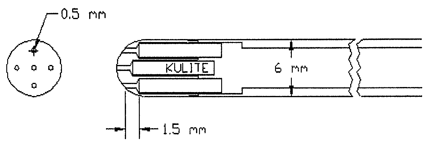
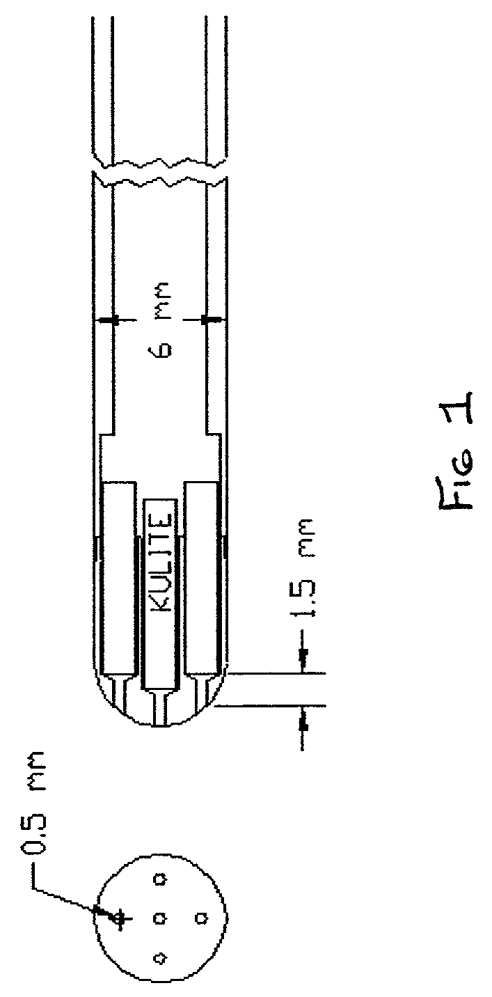
[0061]Referring to FIG. 1 there is shown a typical example of the embodiment for a large 5 or 7-hole probe with miniature pressure transducers embedded at the probe tip. The embodiment, noted as 1, uses a commercially available miniature Kulite XCS-062 pressure sensors. The Kulite XCS-062 is a differential pressure transducer using a fully active Wheatstone bridge on a silicone membrane. The sensors have a high frequency response (50 kHz) and can come in a variety of pressure ranges (the transducers shown in FIG. 1 have a pressure range of plus or minus 5 p...


PUM


Abstract

A high-performance, fast-response, multi-sensor pressure probe for velocity and pressure measurement applications in unsteady and turbulent flowfields. The invention includes both 5 and 7-sensor probes, hemispherical-tip probes and conical-tip probes of various diameters. The present invention eliminates the need for long pressure tubing in such probes by placing the sensors adjacent the flow apertures which leads to a dramatic response in probe measurement frequency response which extends the use of the invention to unsteady and turbulent flows.

Description

[0001]This invention relates to a high-performance, fast-response, multi-sensor pressure probes for velocity and pressure measurement applications in unsteady and turbulent flowfields. It relies on provisional patent application Ser. No. 60 / 260,955 filed on Jan. 12, 2001 by Telionus and Rediniotis and incorporates it by reference herein.THE HISTORY OF THE FIELD[0002]In the past, 5-sensor and 7-sensor, hemispherical-tip and conical-tip probes, of various diameters, have been developed. The present technology eliminates the use of long pressure tubing tubing in conventional 5 and 7 sensor probes by incorporating the pressure sensing transducers close to the probe tip. This, in turn, results in a dramatic increase of the probe measurement frequency response, extending its use to unsteady and turbulent flows. Although the probes developed so far are at least 1.6 mm in diameter, the technology developed in this invention can easily be applied towards the development of smaller probes, by...

Claims


Application Information

Patent Timeline
Patent Type & Authority Patents(United States)
IPC IPC(8): G01F13/00G01P5/165G01P13/02
CPCG01P13/025G01P5/165
Inventor REDINIOTIS, OTHON K.ALLEN, RICHARD D.
Owner AEROPROBE CORP
Why Eureka
Try Eureka