
Throttle valve housing

a technology of valve housing and valve body, which is applied in the direction of valve housing, machine/engine, mechanical apparatus, etc., can solve the problems of complex and expensive production of known throttle valve housing, and achieve the effect of cost-effective and simple production with different shaping

Inactive Publication Date: 2006-03-14
SIEMENS AG
View PDF31 Cites 4 Cited by
  • Summary
  • Abstract
  • Description
  • Claims
  • Application Information

AI Technical Summary

Benefits of technology

This approach simplifies and cost-effectively produces throttle valve housings with different configurations, enabling diverse variants and complex geometries that would be difficult or impossible with integral casting, while reducing production costs and tooling requirements.

Problems solved by technology

The production of the known throttle valve housings is therefore complex and expensive.

Method used


Image

  • Throttle valve housing
  • Throttle valve housing
  • Throttle valve housing

Examples


Embodiment Construction

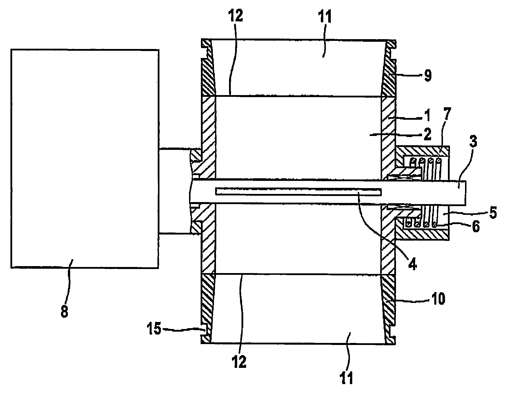
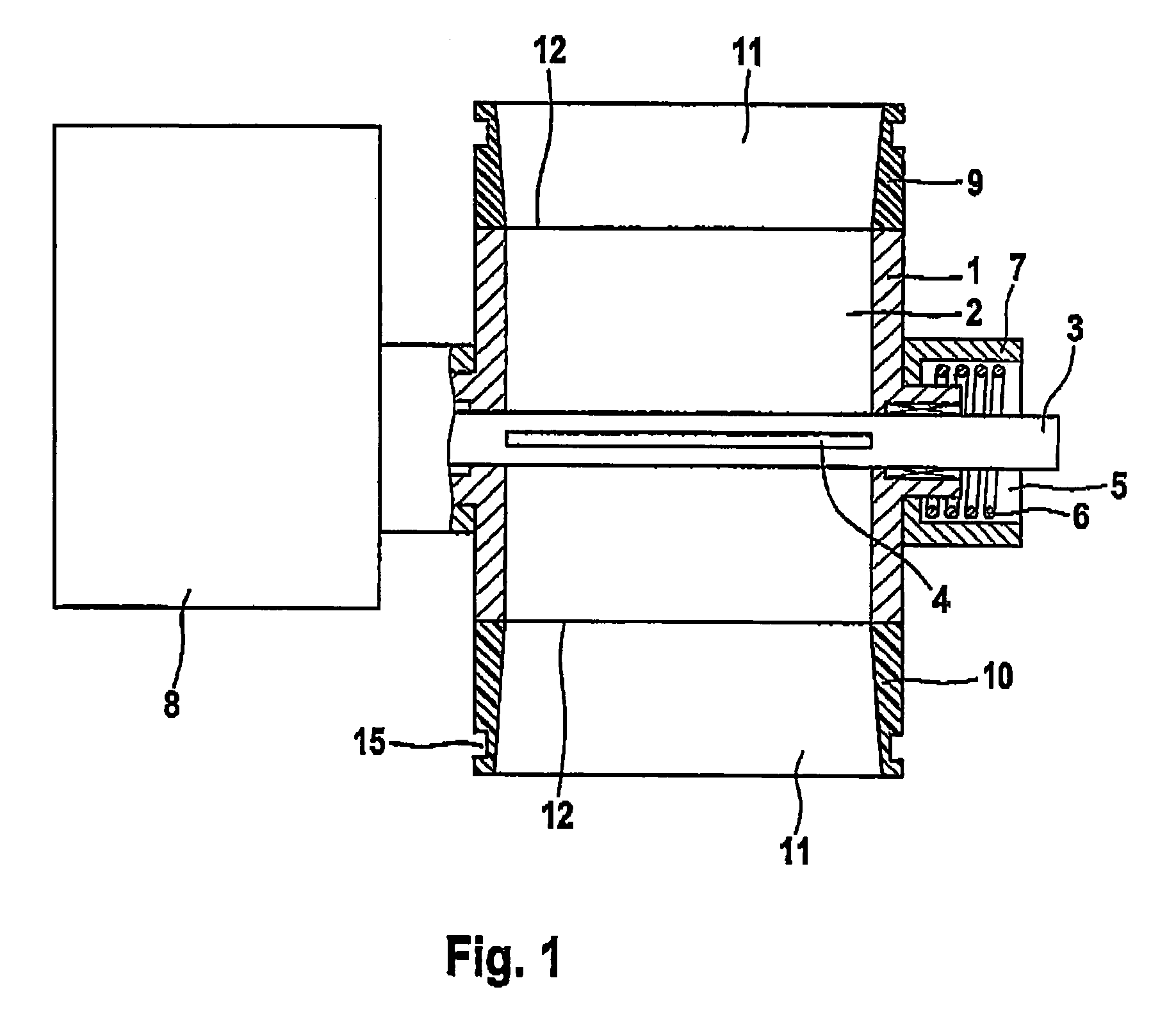
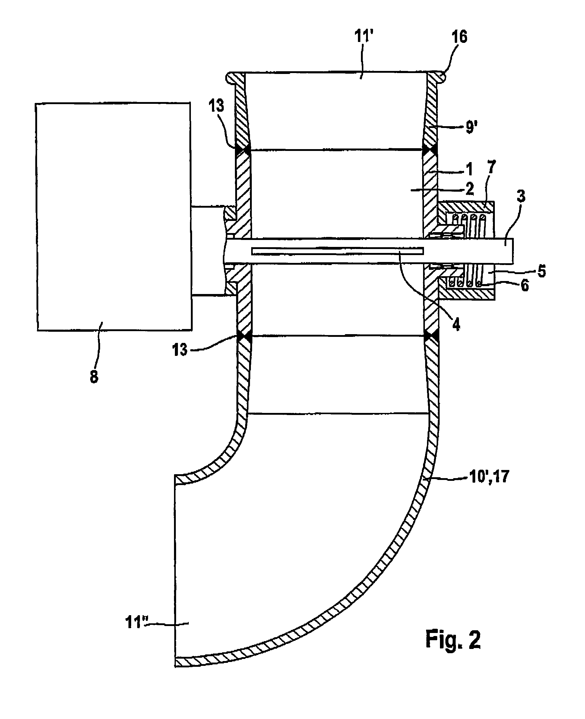
[0027]The throttle valve housings illustrated in the figures all have a tubular housing part 1 of aluminum or an aluminum alloy with a cylindrical flow-through channel 2. A throttle valve shaft 3, on which a throttle valve 4 is arranged to more or less close off the flow-through channel 2, is arranged transversely with respect to the flow-through channel 2 and protrudes with its one end through a corresponding hole in the housing part 1 into a spring chamber 5. Arranged in the spring chamber 5 is a restoring spring 6 which is designed as a torsion spring, surrounds the throttle valve shaft 3 and is fastened at one end to the throttle valve shaft 3 and at its other end to the spring chamber housing 7. The restoring spring 6 pressurizes the throttle valve shaft 3 into the illustrated closed position of the throttle valve 4.

[0028]The other end of the throttle valve shaft 3 protrudes through a corresponding hole in the housing part 1 into an adjusting drive housing 8, in which are arran...


PUM


Abstract

The invention relates to a throttle valve housing, particularly for an internal combustion engine of a motor vehicle, comprising a tubular housing part whose flow-through channel can be closed off from a gaseous medium by means of a throttle valve mounted on a throttle valve shaft. A tubular inlet area and a tubular outlet area are situated at the ends of the housing part, have flow-through openings that extend the flow-through channel, and can be detachably connected to a supply tube and a discharge tube. The inlet area and the outlet area can be produced as separate parts and can be connected to the housing part in a fixed manner.

Description

CROSS REFERENCE TO RELATED APPLICATIONS[0001]The present application is a continuation of international application PCT / DE02 / 03820 filed Oct. 10, 2002, which designated the United States, and further claims priority to German application 10156213.6, filed Nov. 15, 2001, the both of which are herein incorporated by reference.BACKGROUND OF THE INVENTION[0002]The invention is concerned with a throttle valve housing, in particular for an internal combustion engine of a motor vehicle, having a tubular housing part whose flow-through channel can have a gaseous medium, in particular air, flowing through it, can be closed off by means of a throttle valve arranged on a throttle valve shaft and at whose ends are arranged a tubular inlet area and a tubular outlet area which have flow-through openings extending the flow-through channel and can be detachably connected to a supply tube and a discharge tube.[0003]Throttle valve housings of this type are usually injection molded from aluminum and t...

Claims


Application Information

Patent Timeline
Patent Type & Authority Patents(United States)
IPC IPC(8): F02D9/10F02D11/10F16K27/02
CPCF02D9/104F16K27/0218F02D11/10F02D9/107F05C2201/021
Inventor HANNEWALD, THOMAS
Owner SIEMENS AG
Learn More