
Print head energy storage

a technology of energy storage and print head, applied in the field of printers, can solve problems such as confusion, and achieve the effect of reducing the swing of the print head voltag

Inactive Publication Date: 2006-03-14
FUNAI ELECTRIC CO LTD
View PDF15 Cites 0 Cited by
  • Summary
  • Abstract
  • Description
  • Claims
  • Application Information

AI Technical Summary

Benefits of technology

The present invention is about improving the power delivery to ink nozzle firing elements of an ink jet print head. It involves positioning a power supply capacitor on the print head cartridge, which reduces the impedance between the capacitor and the printing elements. This allows for better voltage regulation, reduces the likelihood of damage to the print head electronics due to voltage spiking, and provides better overall power delivery. The capacitor can be attached to the tab circuit with solder or other wire bonding techniques. The invention also includes a method and apparatus for improving the power delivery to the firing elements of an ink jet print head by positioning a power supply capacitor on the print head cartridge. The capacitor can be a surface mount package with a capacitance of about -22 μF. The invention can be used in various types of ink jet printers.

Problems solved by technology

Furthermore, it is not clear from the disclosure of the '969 patent whether or not the capacitor is actually placed on the print head cartridge itself.
However, the capacitor is used to identify the print head cartridge, not reduce the impedance between a power supply capacitor and the firing elements of an ink jet print head.

Method used


Image

  • Print head energy storage
  • Print head energy storage
  • Print head energy storage

Examples


Embodiment Construction

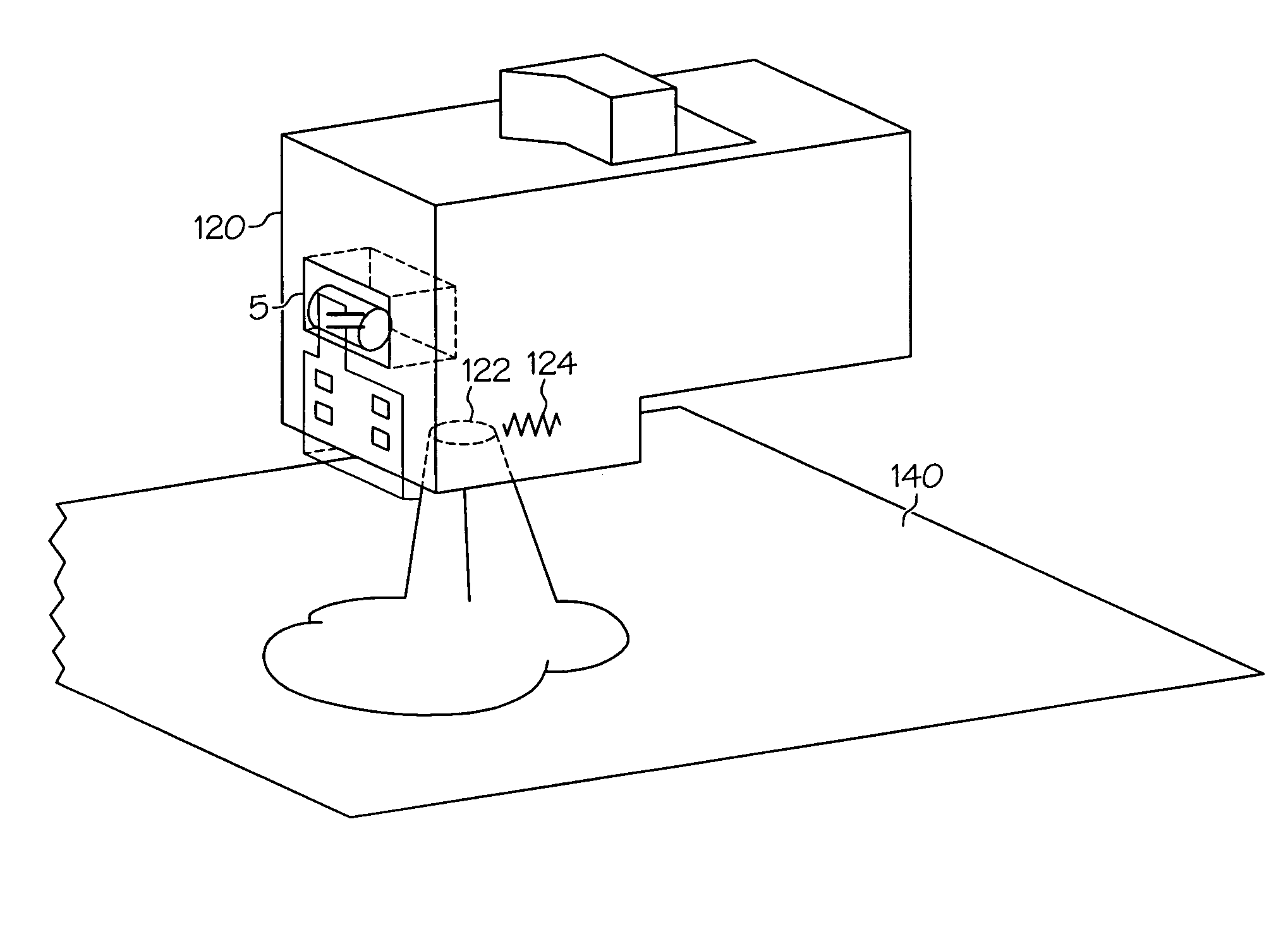
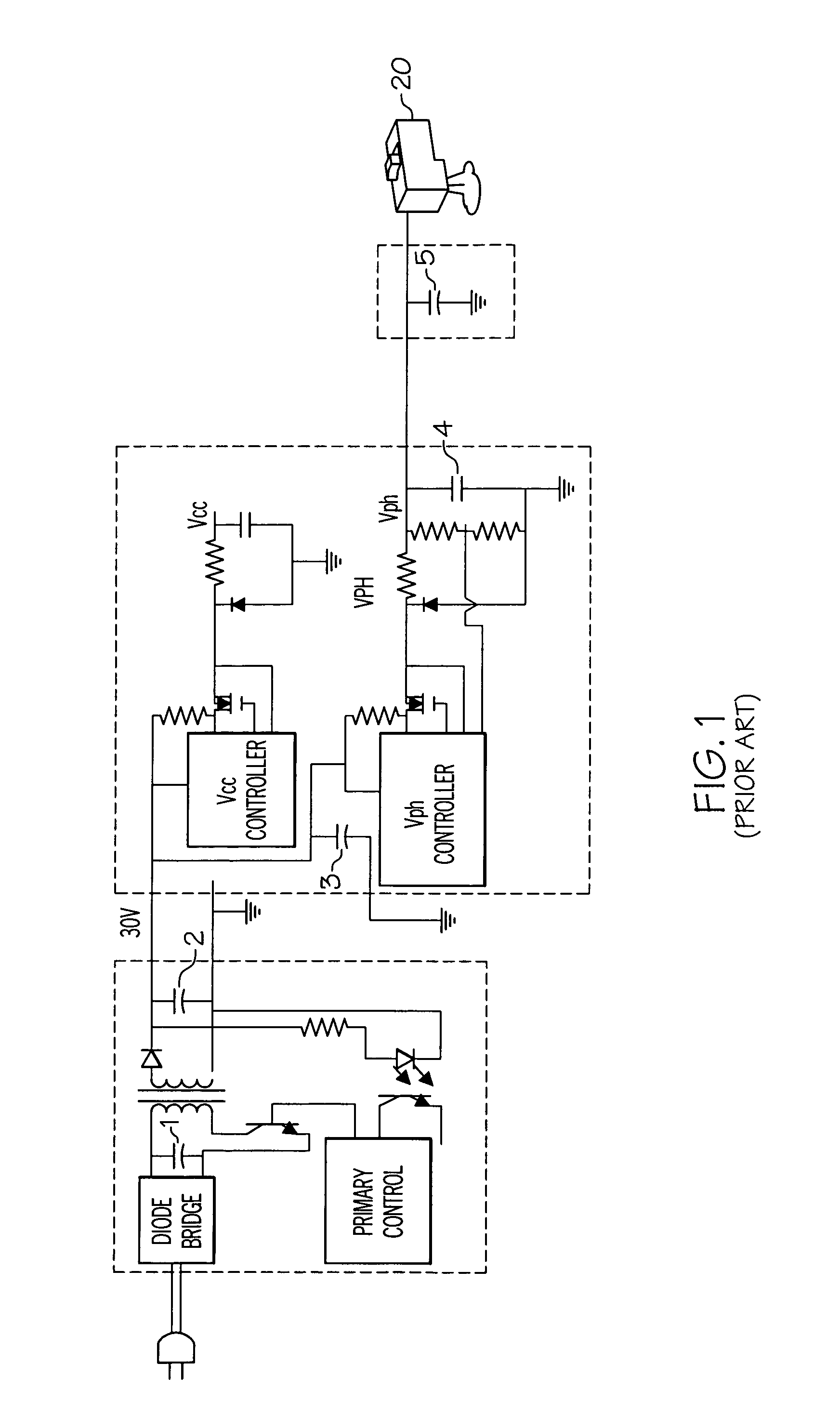
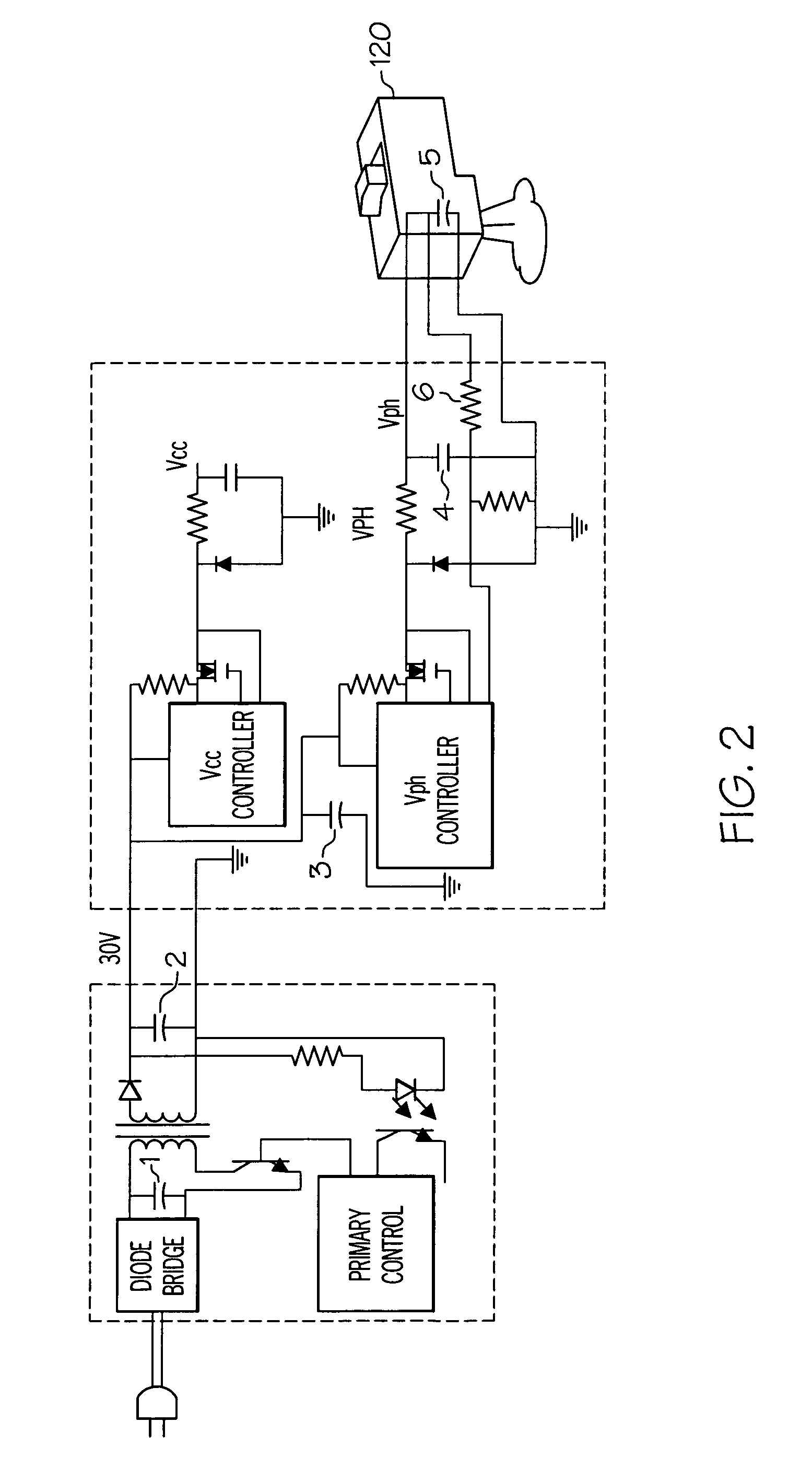
[0033]An embodiment of the present invention includes a method of reducing the Lan impedance, thereby improving the energy distribution to the print head silicon during nozzle firing. This is accomplished by moving capacitor 5 from the carrier circuit board (as shown in FIG. 1) to the print cartridge (as shown in FIGS. 2 and 3).

[0034]In FIGS. 1 and 2, capacitors 1, 2, 3, and 5 are shown as polarized capacitors and capacitor 4 is shown as a non-polarized capacitor; capacitor 5 could be non-polarized.

[0035]FIG. 2 illustrates the movement of the capacitor 5 from the carrier card to the print cartridge. For capacitor 5 to be effective, remote voltage sensing (see sense line 6) improves the power supply loop gain, thus reducing the voltage drop during print head firing.

[0036]Capacitor 5 could be housed in an indentation in the print head next to the tab circuit as shown in FIG. 3. This location for capacitor 5 would be optimized for each print head and one should keep in mind several sys...


PUM


Abstract

The manner in which power is supplied to the firing elements of an ink jet printhead is improved by moving a power supply capacitor from the printer to the print head cartridge to improve the regulation of the supply of power to the firing elements of the print head cartridge. The capacitor can be attached to the tab circuit with solder or other wire bonding techniques. Placing the capacitor on the print head cartridge reduces the impedance between the capacitor and the print head, allows the capacitor to be matched to the print head cartridge firing requirements, allows remote voltage sensing at the print head, provides better voltage regulation at the print head and reduces the likelihood the printhead electronics will be damaged due to voltage spiking.

Description

CROSS-REFERENCE TO RELATED APPLICATIONS[0001]Priority of our U.S. Provisional Patent Application Ser. No. 60 / 483,614, filed 27 Jun. 2003, incorporated herein by reference, is hereby claimed.STATEMENT REGARDING FEDERALLY SPONSORED RESEARCH OR DEVELOPMENT[0002]Not applicableREFERENCE TO A “MICROFICHE APPENDIX”[0003]Not applicableBACKGROUND OF THE INVENTION[0004]1. Field of the Invention[0005]The present invention relates to printers. More particularly, the present invention relates to ink jet printers.[0006]2. General Background of the Invention[0007]The advent of CMOS print heads allowed the integration of print head drivers into the print head silicon. Firing nozzles require a large current in the print head resistor for a very short duration.[0008]Typical ink jet printers have an energy distribution system similar to FIG. 1. Typically, there are five energy storage “capacitors” containing energy supplied to the printer. Print head firing, actual heating of the print head resistor, ...

Claims


Application Information

Patent Timeline
Patent Type & Authority Patents(United States)
IPC IPC(8): B41J2/05B41J29/38
CPCB41J2/04541B41J2/0458B41J2/04548
Inventor ANDERSON, FRANK EDWARDCRONCH, DARELL DEAN
Owner FUNAI ELECTRIC CO LTD
Learn More