
Method for preventing seismic liquefaction of ground in urbanized area and facilities used in this method

a technology of urbanization and seismic liquefaction, which is applied in the direction of soil conditioning compositions, roads, agriculture, etc., can solve the problems of large loss of properties, large casualties, and damage to property, and achieve the effects of preventing seismic liquefaction of ground

Inactive Publication Date: 2006-03-14
SHIRAISHI SHUNTA
View PDF40 Cites 16 Cited by
  • Summary
  • Abstract
  • Description
  • Claims
  • Application Information

AI Technical Summary

Benefits of technology

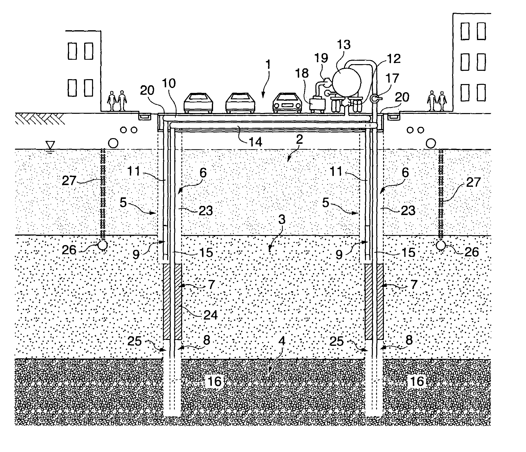
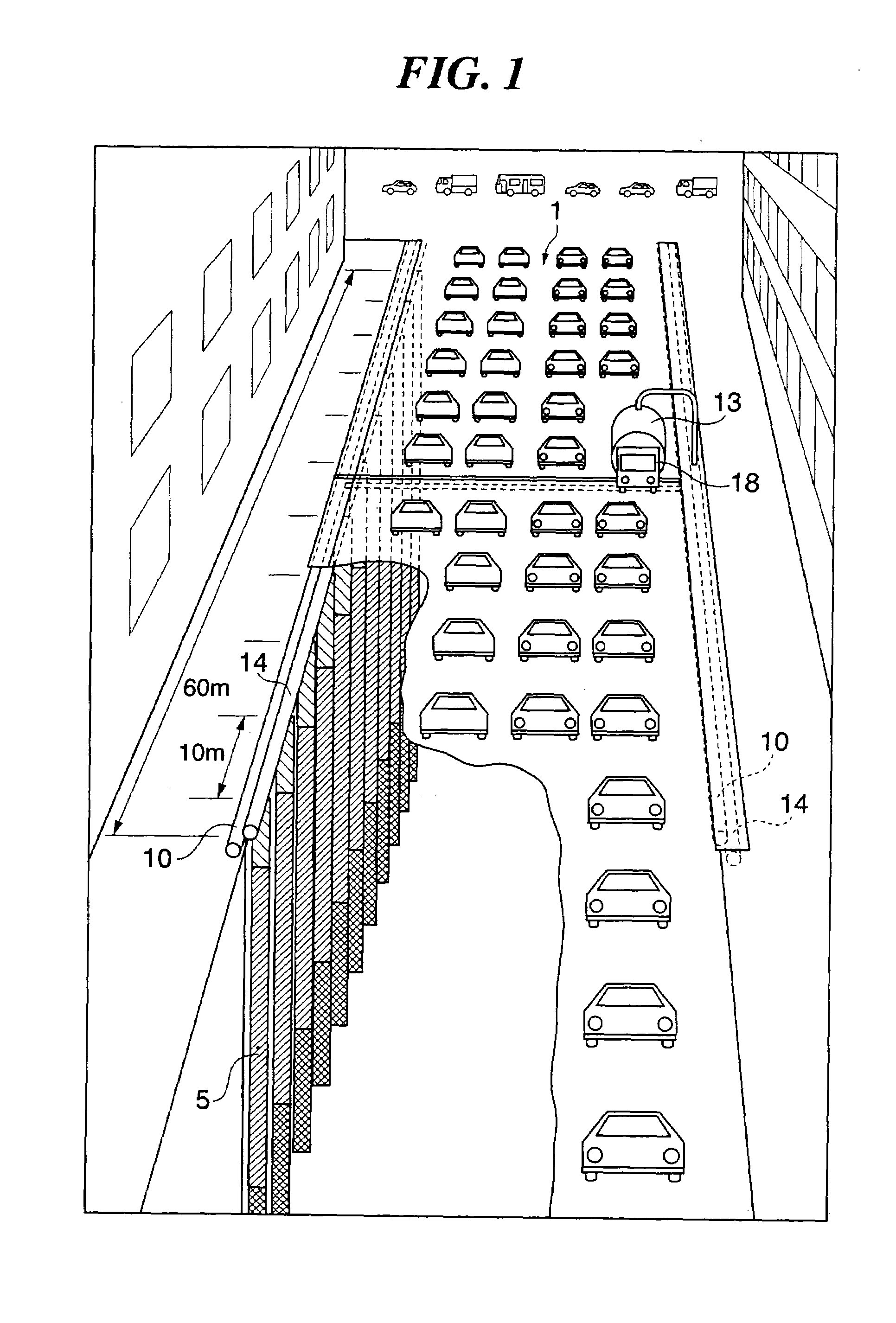
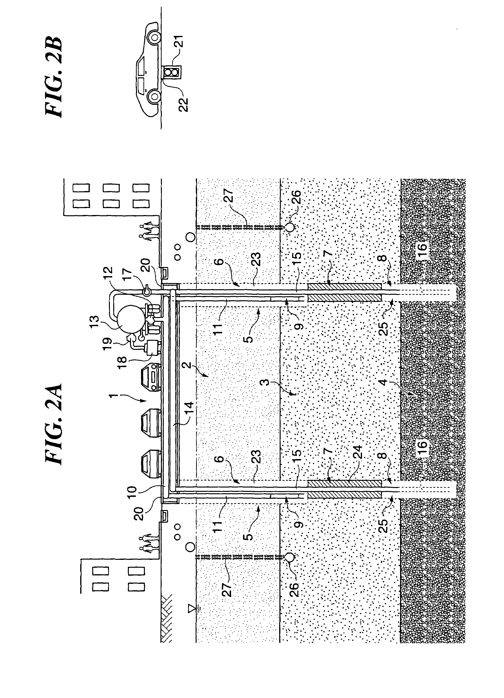
"The present invention provides a method for preventing seismic liquefaction of ground in built-up urbanized areas where there is a loose fine grained layer vulnerable to seismic liquefaction. The method involves lowering the groundwater table in the loose fine grained layer by pumping out the pore water and simultaneously injecting a suitable amount of tap-water into the aerated pore voids of the loose fine grained layer until it is fully filled up. The tap-water is blended with mineral powder to prevent seismic liquefaction. The invention also provides a method for preventing seismic liquefaction by using bored wells and a method for making it easier to prevent harmful uneven settlement caused by the lowering of groundwater table in the loose fine grained layer."

Problems solved by technology

The liquefied ground loses its bearing capacity to cause such a destructive damage as collapse of buildings, bridges, viaducts, wharfs, piers or other types of structure.
Also such a disastrous hazard of an overwhelming fire, a great many casualties and a tremendous loss of properties may be caused by break open buried lifelines of pipes and ducts for feeding water, gas, electric power or for communication lines as the liquefied ground flows slowly toward a low side even on a slope of very slight gradient and the solid ground above the groundwater table where the pipes or ducts of lifelines are buried in it moves together with the flowing liquefied ground beneath the ground water table which induces compression or extraction of the solid ground to tear or crush forcibly the buried lifelines.
The likewise break open of a sub-aqueous tunnel leading into the low level areas may cause deadly flood in the low level area caused by high tide or Tsunami induced by the movement of active faults below sea floor to torture many helpless people by drowning or starving.
However, in violent Hyogoken Nambu Great Earthquake of 1995, liquefaction occurred in the ground of sandy gravel where D50 is much larger than 2.0 mm and in the ground in a loose fill with an “apparent cohesion” containing an appreciable amount of fine particles smaller than 0.074 mm in diameter which behaves like a cohesive soil while it is not fully saturated with the pore water contained in it, its apparent cohesion is lost when it is fully saturated with the pore water in it.
Such a ground with an apparent cohesion is vulnerable to seismic liquefaction, it is found in many cases where the reclaimed fill overlaying the soft cohesive layer called New Bay Mud is prevailing along the sea shores and below the sea bed of San Francisco Bay and California Bay or in the loose fill made of disintegrated soil dredged out of New Bay Mud.
The prior method to increase the density of ground by compacting the ground by means of powerful vibro-hammers or impact hammers mounted on a large crawler-mount pile driving rig and the like is not only very expensive but also extremely difficult to apply in a built-up urban area or in a harbor area where there is not any vacant space which is not occupied by containers. such an activity as busy road traffic nor occupied by containers and / or container lifting cranes installed on wharfs and piers because it requires detouring of traffic or removal of container and cranes to make room for the large pile driving rig with its outriggers fully extended to be ready for its work.
The method using the above mentioned tall large rigs is neither applicable to the place with narrow space nor to the place below an overpass girder where the head clearance is low.
The prior method of solidifying the ground or of replacing the ground with better soil is more expensive than said method of increasing density of ground because the former requires a large amount of chemicals of high price and the latter a large amount of good soil of high price and the cost for removing the original ground and additional cost of a borrow pit and carrying good soil from the borrow pit to refilling site.
Said methods for preventing seismic liquefaction of ground by increasing the density of ground, by solidifying the ground, by replacing the ground with good soil are much too expensive and their application covering wide areas is impracticable because it requires a huge amount of funds which is much in excess of the fund rising ability of any organization concerned.
Prior methods proposed to renew and / or to retrofit the existing structures or underground utilities requires a tremendous amount of funding because there are a great many quantity of the existing structures and / or underground utilities to be renewed and / or retrofitted in a built-up urban area.
Therefore, the application of these methods is practicable only in a very limited scope.
This method involves the problem of land subsidence due to the consolidation of soft strata caused by the lowering of the ground water table and thus its application to built-up urban areas is impracticable.
However, every one of the above quoted patented methods for preventing seismic liquefaction of ground by lowering the saturation degree in ground has the drawback as described in the following paragraph.
However, every one of the above quoted patented methods has a disadvantage in that the air-mixed zone thus formed develops in a limited extent because the countless tiny air bubbles swarmed in said air mixed zone concentrate around the outlet of the source of feeding said air bubbles to minimize further expansion of the air mixed zone.

Method used


Image

  • Method for preventing seismic liquefaction of ground in urbanized area and facilities used in this method
  • Method for preventing seismic liquefaction of ground in urbanized area and facilities used in this method
  • Method for preventing seismic liquefaction of ground in urbanized area and facilities used in this method

Examples


Embodiment Construction

[0105]Further scope of applicability of the present invention will become apparent from the detailed description given hereinafter. However, it should be understood that the detailed description and specific examples, while indicating preferred embodiments of the invention, are given by way of illustration only, since various changes and modifications within the spirit and scope of the invention will become apparent to those skilled in the art from this detailed description.

[0106]To describe a typical application of the present invention in reference to drawings, the present invention as defined in the first object, the second object, the third object, the fourth object, the fifth object, the sixth object, the seventh object, the eighth object and / or the ninth object as well as the tenth object of the present invention is applicable to the ground beneath an urban street in a densely built-up area, a dry riverbed of a river, a ground under water wherever there is not any such an cons...


PUM


Abstract

A method of preventing seismic liquefaction of the ground in an urban area built on reclaimed land consisting of a loose fine grained layer vulnerable to liquefaction underlain with a soft cohesive layer liable to uneven settlement comprising pumping out pore water from the loose fine grained layer to lower the groundwater table to the bottom level of that layer, then injecting into the loose fine grained layer tap water saturated with air and containing micro particles of fly ash or another mineral serving as vehicles of the air into the loose fine grained layer so as to form countless tiny air bubbles and thereby reduce the degree of saturation of that layer to a level preventing seismic liquefaction.

Description

BACKGROUND OF THE INVENTION[0001]1. Field of the Invention[0002]This invention relates to a method for preventing seismic liquefaction of loose alluvial low ground or loose reclaimed ground (hereafter two of them combined called “loose fine grained layer”) in urbanized areas vulnerable to seismic liquefaction, by lowering the saturation degree of groundwater in said loose fine grained layer after pumping groundwater out of said loose fine grained layer.[0003]The invention is applicable to very wide and extensive field of use.[0004]Among those fields of use to which this invention is particularly applicable is the prevention of destructive seismic liquefaction of said fine grained layer in a built-up urbanized area including a harbor area vulnerable to seismic liquefaction which combined with intense tremor causes such damage as collapse of buildings, bridges, viaducts, piers, wharves, and / or outbreaks of fire due to the tremor and catastrophic spreading on of the fire due to a compl...

Claims


Application Information

Patent Timeline
Patent Type & Authority Patents(United States)
IPC IPC(8): E02D3/00E02D3/10E01C3/04E02D1/00E02D27/34
CPCE02D27/34E01C3/04
Inventor SHIRAISHI, SHUNTA
Owner SHIRAISHI SHUNTA
Learn More