Positive displacement pump with a combined inertance value of the inlet flow path smaller than that of the outlet flow path

Active Publication Date: 2006-03-14
SEIKO EPSON CORP
View PDF25 Cites 25 Cited by
  • Summary
  • Abstract
  • Description
  • Claims
  • Application Information

AI Technical Summary

Benefits of technology

[0019]A third pump according to the present invention comprises an actuator which displaces a movable wall such as a piston or diaphragm; a pumping chamber whose volume can be varied by the displacement of the movable wall; an inlet flow path through which a working fluid flows into the pumping chamber; and an outlet flow path through which the working fluid flows out of the pumping chamber, wherein the inlet flow path is

Problems solved by technology

However, the configuration described in Japanese Patent Laid-Open No. 10-220357 requires a check valve both in the inlet and outlet flow paths and has the problem that a fluid passing through two check valves suffers high pressure loss.
Also, the check valves, which open and close repeatedly, are liable to fatigue damage.
Besides, the larger the number of check valves, the lower the reliability.
This results in a significantly low frequency of cycling between the pump's suction and discharge strokes.
However, since the configuration described in Japanese Patent Laid-Open No.08-312537 allows only

Method used


Image

  • Positive displacement pump with a combined inertance value of the inlet flow path smaller than that of the outlet flow path
  • Positive displacement pump with a combined inertance value of the inlet flow path smaller than that of the outlet flow path
  • Positive displacement pump with a combined inertance value of the inlet flow path smaller than that of the outlet flow path

Examples


first embodiment

(1) First Embodiment

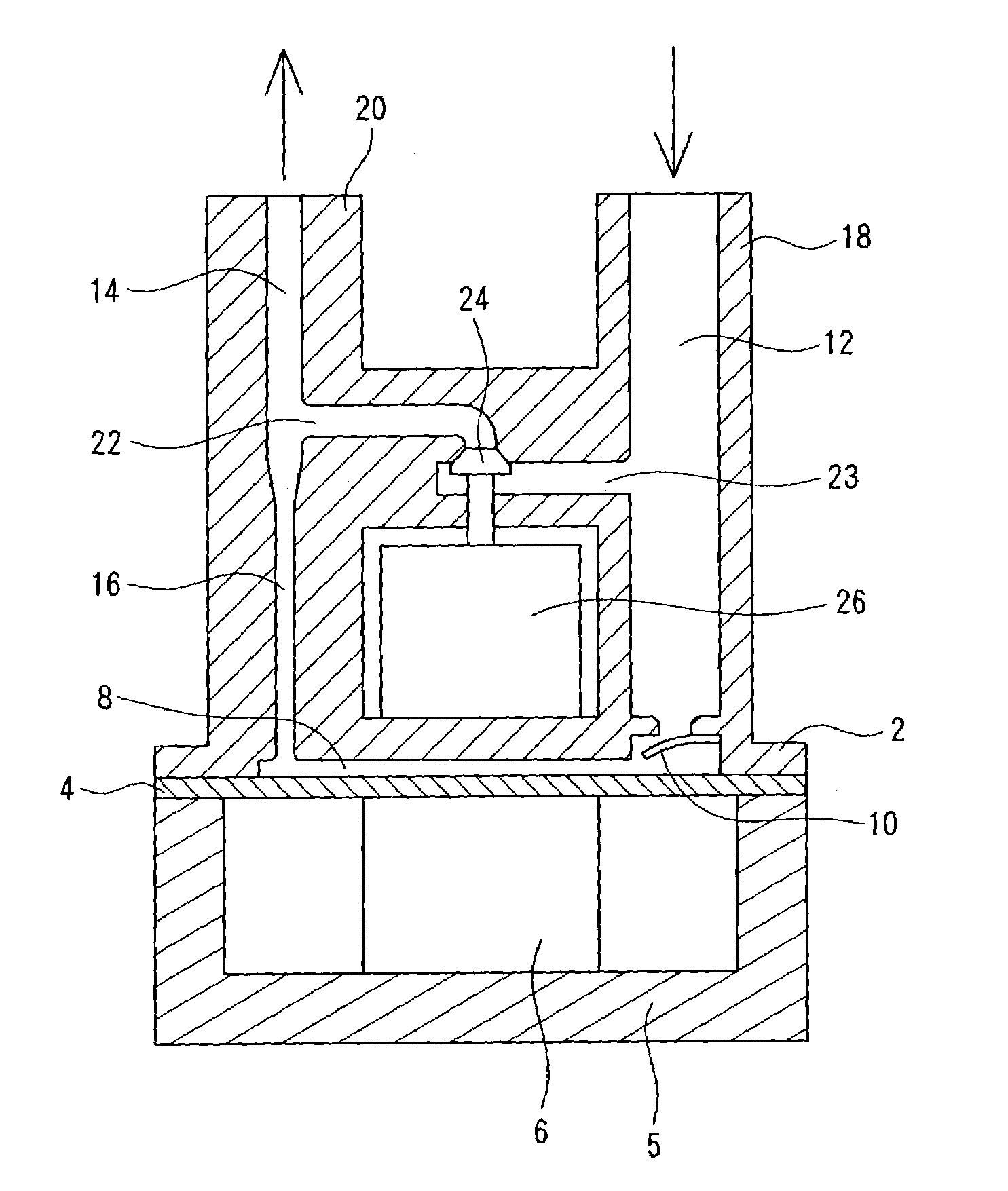
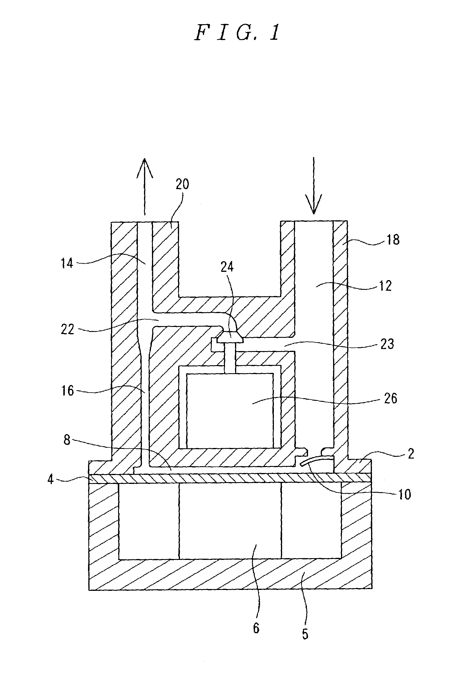
[0038]FIG. 1 is a diagram showing a longitudinal section of a pump according to a first embodiment of the present invention. In FIG. 1, a circular diaphragm 4 is placed at the bottom of a cylindrical casing 2. The diaphragm 4 is free to deform elastically with its rim supported rigidly by the casing 2. At the bottom of the diaphragm 4, a piezoelectric element 6 which expands and contracts in the vertical direction of the figure is installed in its own casing 5 as an actuator for moving the diaphragm 4.

[0039]A narrow space between the diaphragm 4 and the top wall of the casing 2 constitutes a pumping chamber 8. An inlet flow path 12 and an outlet flow path 14 are open to the pumping chamber 8, where in a check valve 10 serving as a fluid resistance element is installed in the inlet flow path 12. Immediately downstream of the pumping chamber 8, the outlet flow path 14 has a narrow segment 16. Part of the circumference of the inlet flow path 12 forms an inlet-side c...

second embodiment

(2) Second Embodiment

[0052]FIG. 3 is a diagram showing a longitudinal section of a pump according to a second embodiment of the present invention. In FIG. 3, a diaphragm 30 is free to deform elastically with its rim supported rigidly by a casing 32. At the bottom of the diaphragm 30, a piezoelectric element 34 which expands and contracts in the vertical direction of the figure is installed as an actuator for moving the diaphragm 30.

[0053]A pumping chamber 36 is formed between the diaphragm 30 and casing 32. The pumping chamber 36 is in communication with a pressure chamber 38 via a connecting flow path 40 which is smaller in cross-sectional area than the pumping chamber 36. The pressure chamber 38 is in communication with an inlet flow path 44 and an outlet flow path 46, wherein a check valve 42 serving as a fluid resistance element is installed in the inlet flow path 44. The check valve 42 is positioned right in front of the connecting flow path 40 which communicates the pumping ch...

third embodiment

(3) Third Embodiment

[0064]Next, a third embodiment of the present invention will be described with reference to FIG. 4.

[0065]The basic configuration in FIG. 4 is similar to that of the second embodiment, but the pumping chamber 36 is filled with fluid and a membrane 50 made of a thin resin film is fixed to the connecting flow path 40. The membrane 50 is capable of deformation equivalent to volume changes of the pumping chamber 36 and has little effect on subtle movements of the working fluid in the connecting flow path 40. For example, even if the connecting flow path 40 has a cross-sectional area 1 / 10 that of the pumping chamber 36, since the amount of expansion / contraction of the piezoelectric element 34 is a few microns, the amount of movement of the working fluid in the connecting flow path 40 is on the order of 10 μm. Consequently, in a small flow of working fluid produced by a piezoelectric element or the like, this is equivalent to a configuration in which the pumping chamber...


PUM


Abstract

A pump according to the present invention has a circular diaphragm 4 placed at the bottom of a casing 2. At the bottom of the diaphragm 4, a piezoelectric element 6 is installed in contact with the diaphragm 4. A narrow space between the diaphragm 4 and the top wall of the casing 2 constitutes a pumping chamber 8. An inlet flow path 12 and an outlet flow path 14 are open to the pumping chamber 8, wherein a check valve 10 is installed in the inlet flow path 12. Immediately downstream of the pumping chamber, the outlet flow path 14 has a narrow segment 16. The narrow segment 16 of the outlet flow path has ½ the diameter and ¼ the cross sectional area of the outlet flow path 14. The outlet flow path 14 has a return inlet 22, which is connected to a return outlet 23 in the inlet flow path via an active valve 24. The active valve 24 is opened and closed freely by an actuator 26 made of shape-memory alloy.

Description

BACKGROUND OF THE INVENTION[0001]1. Field of the Invention[0002]The present invention relates to a positive displacement pump which moves fluid by changing the volume of its pumping chamber with a piston or diaphragm, and, more particularly, it relates to a highly reliable pump with a high flow rate.[0003]2. Description of the Related Art[0004]Conventionally, typical pumps of this type have a check valve installed between an inlet flow path and a variable-volume pumping chamber as well as between an outlet flow path and the pumping chamber, as described, for example, in Japanese Patent Laid-Open No. 10-220357.[0005]Also, there are pumps which produce unidirectional flow by utilizing viscous drag and are configured, for example, as described in Japanese Patent Laid-Open No. 08-312537 such that fluid resistance is larger in the inlet flow path than in the outlet flow path when a valve installed in the outlet flow path is open.[0006]Furthermore, there are pumps which have compression c...

Claims


Application Information

Patent Timeline
IPC IPC(8): F04B43/02F04B43/04F04B49/24F04B53/10
CPCF04B43/046F04B53/1077F04B49/24
Inventor SETO, TAKESHITAKAGI, KUNIHIKO
Owner SEIKO EPSON CORP
Why Eureka
Try Eureka