Pneumatic pogo stick

a technology of pneumatic and spherical sticks, which is applied in the field of pneumatic pogo sticks, can solve the problems of many shortcomings in both construction and functionality, failure to address any of the problems, and over-complex devices, and achieve the effects of smooth ride, preventing jarring of the rider, and smoothly propelling the user several feet off the ground

Inactive Publication Date: 2006-03-14
VURTEGO
View PDF25 Cites 56 Cited by
  • Summary
  • Abstract
  • Description
  • Claims
  • Application Information

AI Technical Summary

Benefits of technology

[0007]It would be a further advantage of the present invention to provide a pneumatic pogo stick that provides a relatively smooth ride especially at the bottom of the compression cycle to prevent jarring of the rider.
[0008]It would be a further advantage of the present invention to provide a pneumatic pogo stick that allows a user to view the internal components of the pogo stick for verification of the integrity of the working parts.
[0009]It would be yet a further advantage of the present invention to provide a pneumatic pogo stick that is capable of smoothly propelling a user several feet off the ground.
[0010]It would be still a further advantage of the present invention to provide a pneumatic pogo stick that is easier to maneuver than other pogo sticks known in the art and that can be easily adjusted to accommodate users of various weights and abilities.
[0011]These and other advantages will become apparent from a reading of ...

Problems solved by technology

Such a pogo stick, however, has many shortcomings in both construction and functionality and fails to address any of the problems encountered when attempting to use compressed air as a spring, such as smoothness ...

Method used


Image

  • Pneumatic pogo stick
  • Pneumatic pogo stick
  • Pneumatic pogo stick

Examples


Embodiment Construction

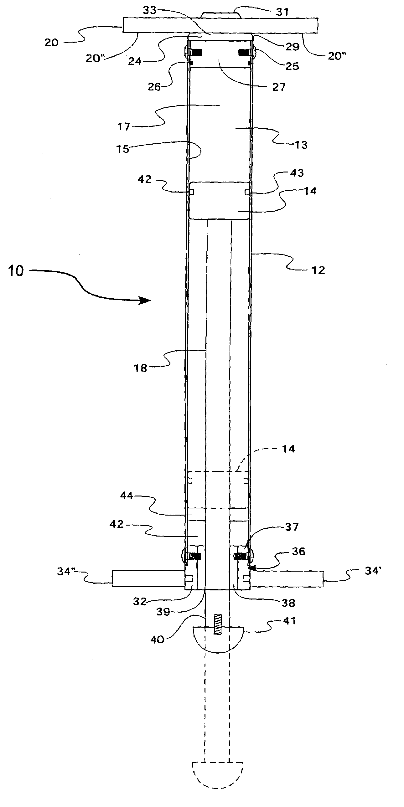
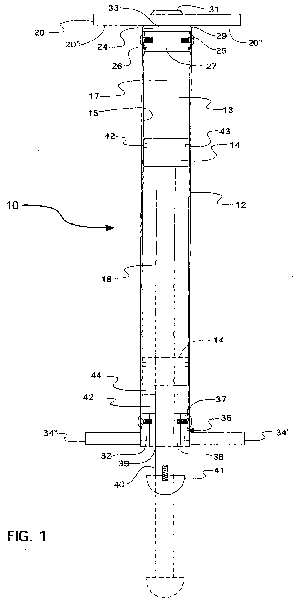
[0045]FIG. 1 illustrates a first embodiment of a pneumatic pogo stick, generally indicated at 10, in accordance with the principles of the present invention. The pogo stick 10 is comprised of a plastic tube 12 which forms an outside housing to which various other components of the device are attached and a cylinder portion 15 of a piston 14 / cylinder 15 arrangement. Plastics such as PVC or polycarbonate are preferable over other materials including steel and aluminum because they are strong, lightweight, resilient, inexpensive, and dent resistant. An alternate material that could be used for the cylinder 12 is cellulose acetate butyrate. Such plastic materials are preferred since metals such as aluminum or steel, if dented, may cause the pogo stick to leak air between the cylinder 15 and piston 14 during use or partially or fully obstruct movement of the piston 14 relative to the cylinder 15 so that the device 10 is no longer operable. Thus, despite side impacts, the cylinder 15 must...


PUM


Abstract

A pneumatic pogo stick is comprised of an elongate cylindrical housing which forms a cylinder. The housing is formed from a clear polycarbonate plastic. A top cap is attached to one end of the housing to form the top of an air chamber. A plastic piston, slidable within the cylinder, forms the bottom of the air chamber. An elongate shaft is coupled to the bottom of the piston and is moveable therewith, extending from the distal end of said housing as the piston moves within the cylinder. A bottom bracket assembly is attached to the bottom of the housing and a bushing for maintaining the lateral position of the shaft relative to the housing is attached to the bottom bracket assembly. The bushing prevents the shaft from rotating relative to the housing. User foot supports are also attached to the bottom bracket for supporting the feet of the user and handle bars are attached to the top cap for grasping with the hands of a user.

Description

CROSS-REFERENCE TO RELATED APPLICATION[0001]The present application claims priority to U.S. Provisional Patent Application Ser. No. 60 / 335,524 filed on Oct. 19, 2001.FIELD OF THE INVENTION[0002]The present invention related generally to a pogo stick, and more specifically, to a pneumatic pogo stick that utilizes lightweight and durable materials to maximize the performance and reliability of a pneumatic pogo stick.BACKGROUND OF THE INVENTION[0003]A conventional pogo stick utilizes a coil spring within a hollow tube housing to create an upward force when compressed by a user to propel the user in an upward direction. In order to get more lift than can be provided with a coil spring and without increasing the weight of the pogo stick itself, it has been recognized in the art that an air filled cylinder / piston arrangement can produce increased propulsion or lift for the same length of stroke. Some have gone so far as incorporating engine power in order to increase lift and provide a po...

Claims


Application Information

Patent Timeline
IPC IPC(8): A63B25/08A63B21/008
CPCA63B25/08A63B2208/12
Inventor SPENCER, BRUCE L.
Owner VURTEGO
Why Eureka
Try Eureka