Connector for attaching an alignment rod to a bone structure

a technology of connecting rods and bones, applied in the field of spinal alignment systems, can solve the problems of system failure, loss of desired spine position, and failure of the hook and rod system, and achieve the effect of minimizing the adverse effects

Inactive Publication Date: 2006-03-14
EDWARD L LEWIS
View PDF24 Cites 41 Cited by
  • Summary
  • Abstract
  • Description
  • Claims
  • Application Information

AI Technical Summary

Benefits of technology

[0014]The invention solves the problems and / or overcomes the drawbacks and disadvantages of the prior art by minimizing the adverse effects of the tensile and compression forces acting on the various securements of the spinal alignment system. In particular, the invention accomplishes this by providing a connector for a spinal alignment system including a base, a hook, a guide aperture, and a locking portion. The base includes a channel extending therethrough to receive a fixation rod. The hook extends from the base. The guide aperture is adapted to receive a bone fastener and the locking portion is adapted to engage the bone fastener. The guide aperture extends through one of the base member and the hook member and the locking portion is located in the other of the base and the hook. The locking portion is coaxial with the guide aperture such that the guide aperture guides a shaft of the bone fastener into alignment with the locking portion when the bone fastener is received by the guide aperture.

Problems solved by technology

This pulling force at the ends of the rod can be of such magnitude that the hook and rod system can fail.
Regardless, the desired position of the spine can be lost.
Hook pull off and failure is not limited to the compression mode, it is also a problem in the distraction mode for this type of system.
In addition, the ratcheted rods in the distraction mode could break at the ratchet points, again causing system failure.
Moreover, because the bone of the vertebrae is mostly cancellous and is relatively weak, it is not a preferred bone type for thread fixation.
The weaker bone material is more likely to fail than the screw.
As a result, the screws that are subject to the pulling forces described above can experience pull out and failure.
But these larger features can disrupt too much of the vertebrae and cause the vertebrae to fracture, independent of screw pull out.
However, the screw is still subject to failure by pull out and the threads can still cause the vertebra to fracture.
But use of both a hook and a screw does not eliminate the problems associated with each.
The hook can still experience slippage and the screw can still experience pull out.
Although these devices can provide for a more reliable mounting of the rod onto the spinal column over other devices, these devices, as stated above, cannot eliminate hook slippage and bone screw pull out.
But nuts used on the far side of the screw in the spine are difficult to place and to hold until secure.
The screw can be sharp, tearing gloves, exposing skin or even cutting the surgeon.
Also, for the nut to relieve the screw threads from being the sole resistance force to pull out, the nut must be sufficiently tight against the bone, which is difficult to achieve by hand (without a holding device so that the nut does not spin while tightening is occurring).
The use of a nut with the screw can be a difficult, cumbersome and time consuming procedure at best.

Method used


Image

  • Connector for attaching an alignment rod to a bone structure
  • Connector for attaching an alignment rod to a bone structure
  • Connector for attaching an alignment rod to a bone structure

Examples


second embodiment

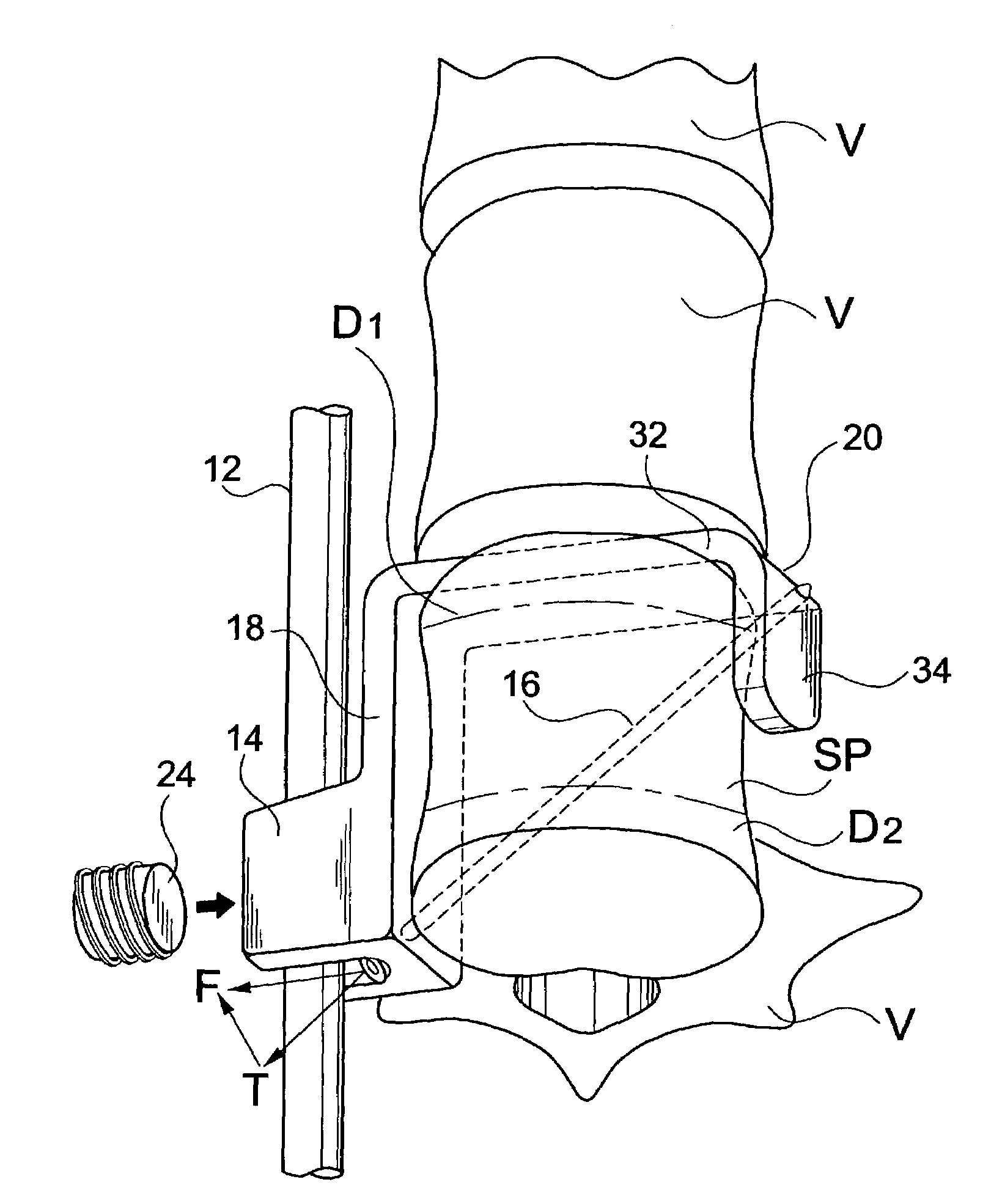
[0063]As discussed above, the bone fastener 16 can be disposed at any angle and can pass through different parts of connector 14. Examples of alternative embodiments in this regard are now described with reference to FIGS. 6A–6F. In FIG. 6A, a connector 114 includes a base 118 and a first portion 132 of a hook 120 extending from the base 118 adjacent the second open end 144 of a channel 122 formed in the base 118. A guide aperture 128 extends through the channel 122 adjacent the second open end 144 of the channel 122. A second hook portion 134 extends from the first hook portion 132 and is longer as compared to the second hook portion 34 of the connector 14, as illustrated in FIGS. 2–5. A threaded bore 130 is located adjacent the free end of second hook portion 134 of the hook 120.

third embodiment

[0064]FIG. 6B illustrates the connector 214 including a base 218 and a first portion 232 of a hook 220 extending from the base 218 adjacent the second open end 244 of a channel 222 formed in the base 218. A second hook portion 234 extends from the first hook portion 232 and is longer as compared to the second hook portion 34 of the connector 14, as illustrated in FIGS. 2–5. The connector 214 includes a guide aperture 228 extending through the channel 222 adjacent the first open end 242 of the channel 222 and a threaded bore 230 adjacent the free end of the second hook portion 234 of the hook 220. The bone fastener 16 is inserted through the guide aperture 228 and threaded into the threaded bore 230.

[0065]FIG. 6C illustrates a fourth embodiment of the connector 314. Like the first embodiment of FIGS. 2–5, the connector 314 includes a base 318 and a first portion 332 of a hook 320 extending from the base 318 adjacent the second open end 344 of a channel 322 formed in the base 318. A g...

fifth embodiment

[0066]FIG. 6D illustrates the connector 414. The connector 414 includes a base 418 and a first portion 432 of a hook 420 extending from the base 418 adjacent the second open end 444 of a channel 422 formed in the base 418. A guide aperture 454 extends through the first hook portion 432. A second hook portion 434 extends from the first hook portion 432 and is lengthened compared to the second hook portion 34 of the connector 14, as illustrated in FIGS. 2–5. A threaded bore 430 is located adjacent the free end of the second hook portion 432 of the hook 420. The bone fastener 16 is inserted through the guide aperture 454 and threaded into the threaded bore 430.


PUM


Abstract

A connector for a spinal alignment system includes a base, a hook, a guide aperture, and a locking portion. The base includes a channel extending therethrough to receive a fixation rod. The hook extends from the base. The guide aperture is adapted to receive a bone fastener and the locking portion is adapted to engage the bone fastener. The guide aperture extends through one of the base and the hook and the locking portion is located in the other of the base and the hook. The locking portion is coaxial with the guide aperture such that the guide aperture guides a shaft of the bone fastener into alignment with the locking portion when the bone fastener is received by the guide aperture. The bone fastener cooperates with the base and hook to form a tension band construct that resists opposing forces acting on the construct. A rod locking fastener engages the channel and the fixation rod to secure the fixation rod in the channel.

Description

BACKGROUND OF THE INVENTION[0001]1. Field of the Invention[0002]The invention relates generally to a spinal alignment system for treating spinal deformities and / or injuries and, more particularly, to securing a spinal alignment system to a spinal column.[0003]2. Description of the Related Art[0004]Deformities of the spine and injuries to the spine have long been treated by surgical intervention. In treating deformities and injuries to the spine, the goal is to return the spine, to the extent possible, back to a normal curvature and / or hold it in a desired position. Several surgical intervention techniques and devices have been proposed for the treatment of injuries to and deformities of the spine.[0005]Some of these surgical techniques use a hook and rod system to hold the spine in a desired position. In such systems, the rod can be placed along the outside of the curved spine, that is on the convex side, and can be attached to the vertebrae of the spine by hooks as illustrated in F...

Claims


Application Information

Patent Timeline
Patent Type & Authority Patents(United States)
IPC IPC(8): A61B17/58A61B17/70
CPCA61B17/7056A61B17/7032A61B17/7008
Inventor LEWIS, EDWARD L.NUZZO, ROY M.
Owner EDWARD L LEWIS
Why Eureka
Try Eureka