Incising apparatus for use in cataract surgery

a technology for cataract surgery and cutting equipment, which is applied in the field of ophthalmology, can solve the problems of reducing the clarity of a patient's vision, prolonging the tedious process, and inadvertent leakage of viscoelastic material from the larger corneal incision, etc., and achieves the effects of simple, convenient and fast operation, and convenient manufacturing

Inactive Publication Date: 2006-03-14
FEINSOD MATTHEW
View PDF9 Cites 28 Cited by
  • Summary
  • Abstract
  • Description
  • Claims
  • Application Information

AI Technical Summary

Benefits of technology

[0018]Generally speaking, in accordance with the invention, an incising apparatus for use in the field of ophthalmology, and more specifically for use during cataract surgery is provided. An incising apparatus for making a circular incision in the anterior lens capsule to obtain access to the native lens for extraction is disclosed. The instrument comprises a safe, simple, inexpensive device, and includes a handle and a circular band with a sharp bottom edge that is deformable upon compression into a very thin, almost flattened ellipse. The invention differs from existing prior art instruments in that it involves no intricate hinges or moving parts, and that it may be inserted through a narrower incision in the outer layers of the eye of a patient. Thus, the incising apparatus of the invention is much less complex, more durable, safer, easier to manufacture and more cost-effective than prior art apparatuses. It is intended for single usage in its preferred embodiment, and is therefore disposable.

Problems solved by technology

Cataracts occur when the lens substance opacifies, obscuring the passage of light therethrough and resulting in a decrease in the clarity of a patient's vision.
Often, during insertion and manipulation of the forceps, some viscoelastic material inadvertently leaks from the larger corneal incision.
This prolongs the tedious process and increases the risk of error such as a radial tear in the anterior capsule.
Because the anterior lens capsule is similar to a cellophane wrapping material, the tear is frequently inadvertently initiated in an undesirable direction, leading to such a dangerous radial tear.
A radial tear is dangerous because it results in decreased structural integrity of the lens capsule, and may lead to serious complications, such as the lens falling to the back of the eye or the spillage of vitreous into the anterior chamber intraoperatively.
Due to the technical difficulty in achieving a capsular opening of optimal size and shape, the anterior capsulorrhexis step may be unreliable, unpredictable, and inconsistent.
The disadvantage of this incising apparatus described in Smirmaul is that it requires a wide passage wound cut on the corneoscleral tissue.
However, none of these apparatus adequately perform their job and are sufficiently complicated and expensive.

Method used


Image

  • Incising apparatus for use in cataract surgery
  • Incising apparatus for use in cataract surgery
  • Incising apparatus for use in cataract surgery

Examples


first embodiment

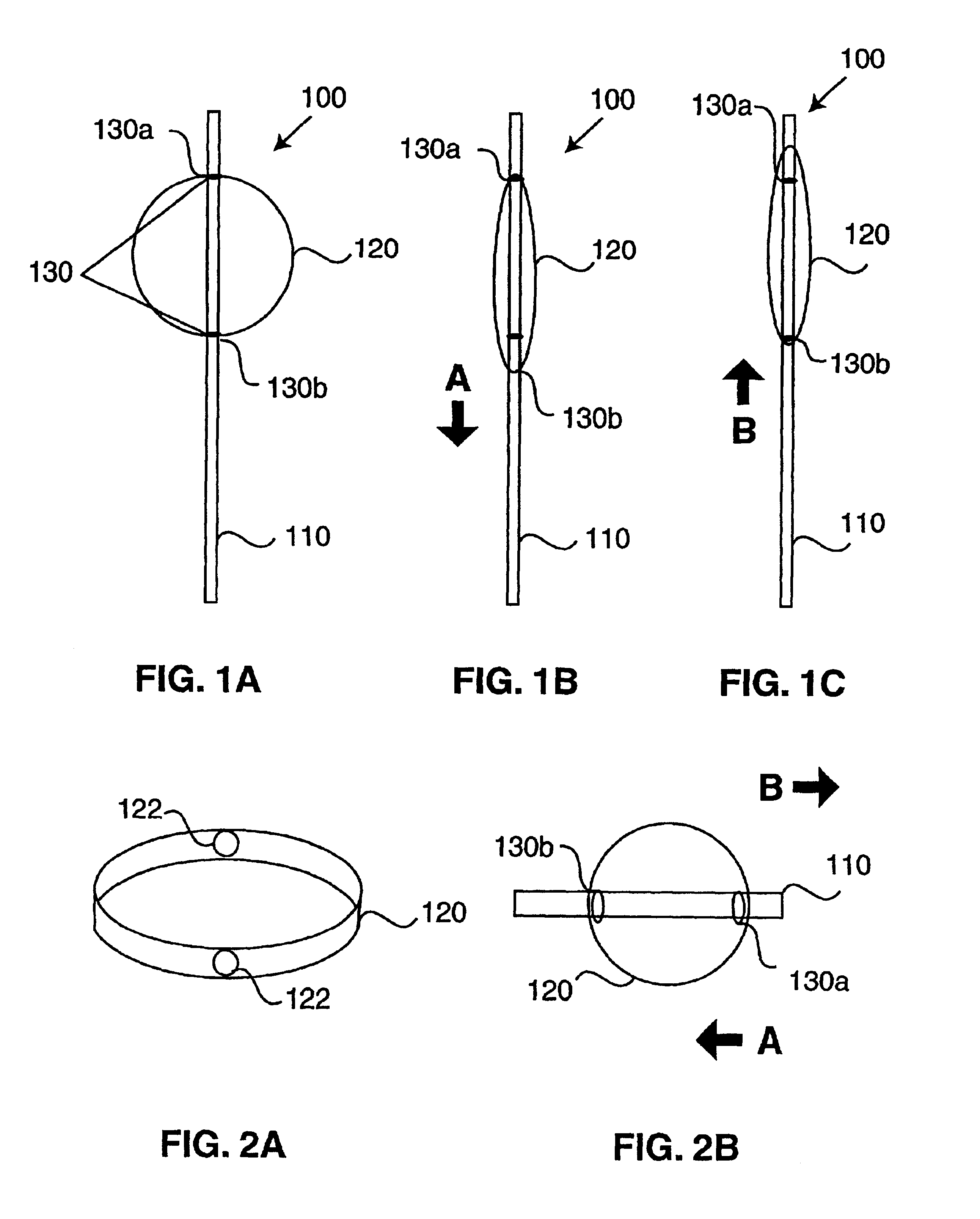
[0030]Referring first to FIGS. 1-2A, an incising apparatus 100 constructed in accordance with the invention is shown. As is first depicted in FIG. 1, incising apparatus 100 comprises a handle portion 110, a circular cutting band 120, and a pair of stoppers 130 (130a, 130b) positioned along handle 110, along the interior circumference of circular cutting band 120, and positioned so that circular cutting band 120 is maintained in its circular shape. Circular cutting band 120 is slidably attached to handle 110 so that, as noted above, stoppers 130 are positioned inside the circular cutting band. Therefore, as shown in FIG. 1A, the top portion of the circular cutting band in the vicinity of stopper 130a can move in a direction up in FIG. 1A, but is restricted from moving down along handle 110 by stopper 130a. Similarly, the bottom portion of circular cutting band 120 in the vicinity of stopper 130B is able to slide along handle 110 in a downward position in FIG. 1A, but is restricted in...

second embodiment

[0036]Referring next to FIGS. 3A-3C, an incising apparatus constructed in accordance with the invention will now be described.

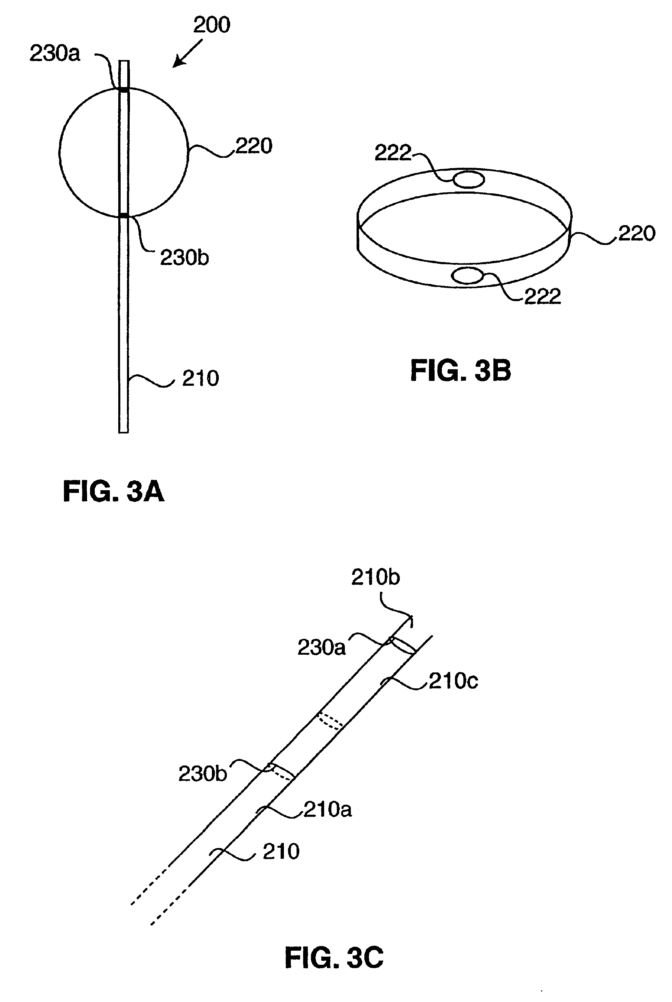
[0037]As is shown in FIG. 3A an incising apparatus 200 constructed in accordance with the second embodiment includes a handle 210, a circular band 220, and integral cylindrical stopping faces 230a and 230b. While integral cylindrical stopper faces 230a and 230b function similarly to stoppers 130a and 130b of FIG. 1A, these stopper faces are formed integral with handle 210. Therefore, as is shown in FIG. 3C, integral cylindrical stopper faces 230a and 230b form a transition from a flat compressed portion of handle (compressed portion 210a and 210b of handle 210) and a cylindrical portion 210c of handle 210. Because as is shown in FIG. 3B, circular band 220 is formed with oval holes 222, these oval holes are structured so as to slide freely along flattened portions 210a and 210b of handle 210, but to be restricted in their movement upon contact with integral st...

third embodiment

[0044]Referring next to FIGS. 6 and 7, an incising apparatus constructed in accordance with the invention is shown.

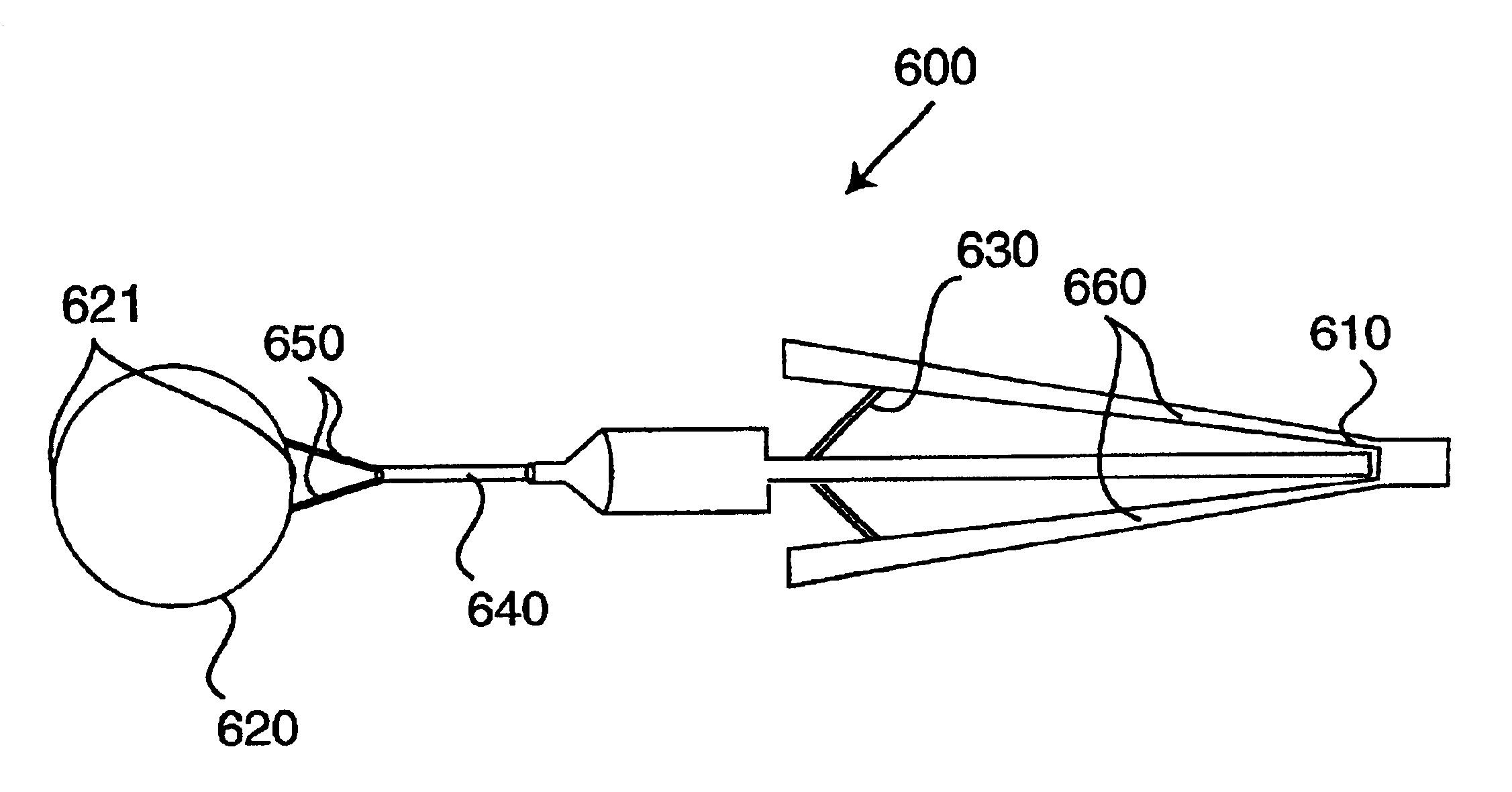
[0045]As is shown in FIG. 6, an incising apparatus 600 includes a gripping handle 610 having pressure members 660, and biasing members 630. FIG. 6 shows handle 610 in an open position. Also included is a tubular component 640, and two arms 650 protruding from a distal end thereof. A circular cutting ring 620 is attached to the two arms, which as shown in 600 are open in their natural state, but which may be compressed together like forceps by the compression of pressure members 660. Circular cutting band 620 is provided with creases 621 at the 6 and 12 o'clock positions as shown in the prior embodiments. Upon compression of pressure members 660 against the force of biasing members 630, the structure of incising apparatus 600 changes to that shown in FIG. 7. As is shown in FIG. 7, elements 660 have been compressed against the biasing force of bias springs 630 through an ...


PUM


Abstract

An incising apparatus for cataract surgery is provided. The incising apparatus includes a handle having a proximal end and a distal end. A circular cutting band is adapted to slide along the handle. At least one stopper element is provided in the vicinity of the proximal end of the handle. The at least one stopper element is positioned within the interior of the circular band so as to restrict the motion of the circular band relative to the handle.

Description

CROSS REFERENCE TO RELATED APPLICATIONS[0001]This application is a continuation of application Ser. No. 09 / 507,703, filed Feb. 18, 2000, now U.S. Pat. No. 6,379,370.BACKGROUND OF THE INVENTION[0002]1. Field of the Invention[0003]The invention relates generally to an apparatus used in the field of ophthalmology and more particularly to an incising apparatus used in cataract surgery.[0004]2. Description of the Related Art[0005]The lens of a human eye is a transparent, biconvex crystalline structure located just behind the iris of the eye. The lens substance is contained within an elastic, transparent lens capsule, similar in structure to the substance of a grape being held inside its skin. This lens capsule has a relatively thin cross section, with an average thickness of between 14 microns to 21 microns at its anterior surface.[0006]Cataracts occur when the lens substance opacifies, obscuring the passage of light therethrough and resulting in a decrease in the clarity of a patient's ...

Claims


Application Information

Patent Timeline
Patent Type & Authority Patents(United States)
IPC IPC(8): A61F9/00A61F9/007
CPCA61F9/00754
Inventor FEINSOD, MATTHEW
Owner FEINSOD MATTHEW
Why Eureka
Try Eureka