Fluorescent lamp lighting device

a technology for fluorescent lamps and lighting devices, which is applied in the direction of transit-tube circuit elements, lighting and heating apparatus, cathode-ray/electron beam tube circuit elements, etc. it can solve the problems of long reset time, difficulty in ntc thermistor cooling, and inability to maintain the pre-heating efficiency of the filament, so as to prevent the number of on-off operations of the lamp. , the effect of reducing the number of lamps

Inactive Publication Date: 2006-03-14
MURATA MFG CO LTD
View PDF14 Cites 15 Cited by
  • Summary
  • Abstract
  • Description
  • Claims
  • Application Information

AI Technical Summary

Benefits of technology

[0012]In order to overcome the problems described above, preferred embodiments of the present invention provide a fluorescent lamp lighting device in which the problem of the reset time becoming long is overcome and a decrease in the number of on-off operations of the lamp can be prevented.
[0016]Since a surface-mount-type NTC thermistor is used, when compared to a reed-type NTC thermistor, generated heat is easily radiated to the circuit substrate, and thus, the device can easily return to room temperature. As a result, at the restarting time, the surface-mount-type NTC thermistor is more likely to return to a state in which the resistance value is high, and before the lamp is started, a state in which pre-heating current flows through an electrode filament coil can be reached more quickly.
[0018]Therefore, it becomes easier to ensure pre-heating current which flows through the electrode filament. Also, a decrease in the number of on-off operations of the lamp due to insufficient pre-heating can be prevented.

Problems solved by technology

Furthermore, when a component which is close to an NTC thermistor is a self-heating component, such as a PTC thermistor, it becomes difficult for the NTC thermistor to cool due to the self-heating, and the off time required to maintain the pre-heating efficiency of the filament, that is, the reset time, becomes long.
Therefore, at the restarting time, since it is difficult to ensure pre-heating current which flows through the electrode filament, there is a risk in that the number of on-off operations of the lamp may be decreased due to insufficient pre-heating.

Method used


Image

  • Fluorescent lamp lighting device
  • Fluorescent lamp lighting device
  • Fluorescent lamp lighting device

Examples


Embodiment Construction

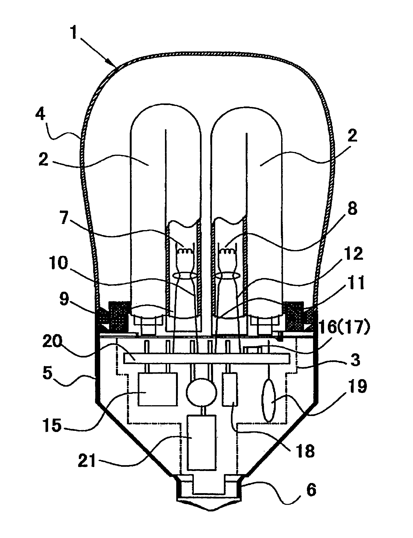
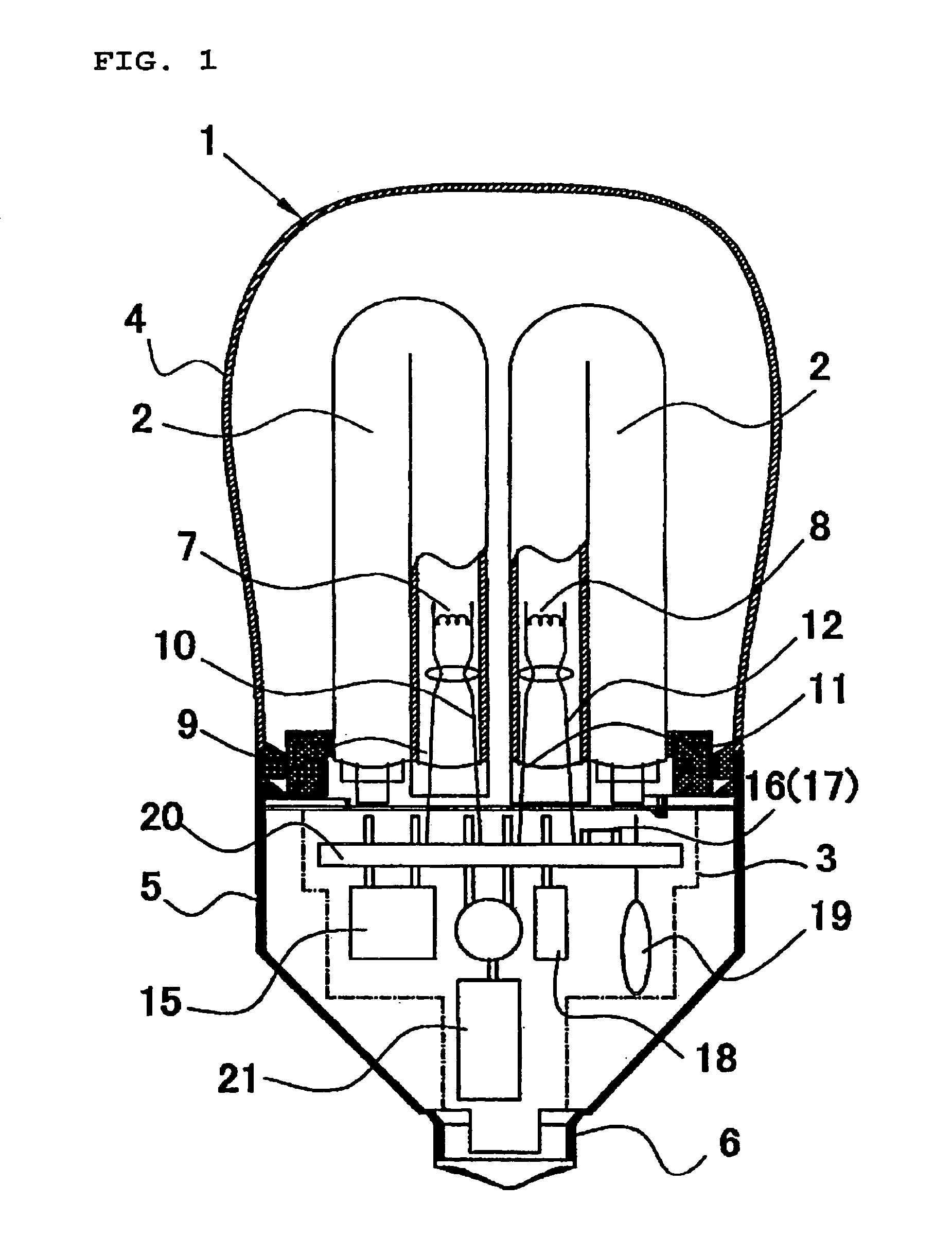
[0024]The configuration of a fluorescent lamp lighting device of a preferred embodiment will be described first. FIG. 1 is a sectional view showing the configuration of a fluorescent lamp lighting device according to this preferred embodiment.

[0025]An electric-lamp-type fluorescent lamp 1 includes a fluorescent light bulb 2, an external-tube glass bulb 4 which covers the fluorescent light bulb 2, a resin case 5 connected to the base-portion side of the external-tube glass bulb 4, an electronic lighting circuit 3 housed in the resin case 5, and a base 6 arranged at the end portion of the resin case 5. The fluorescent light bulb 2 preferably includes four substantially U-shaped glass tubes (only two substantially U-shaped glass tubes are shown in the figure).

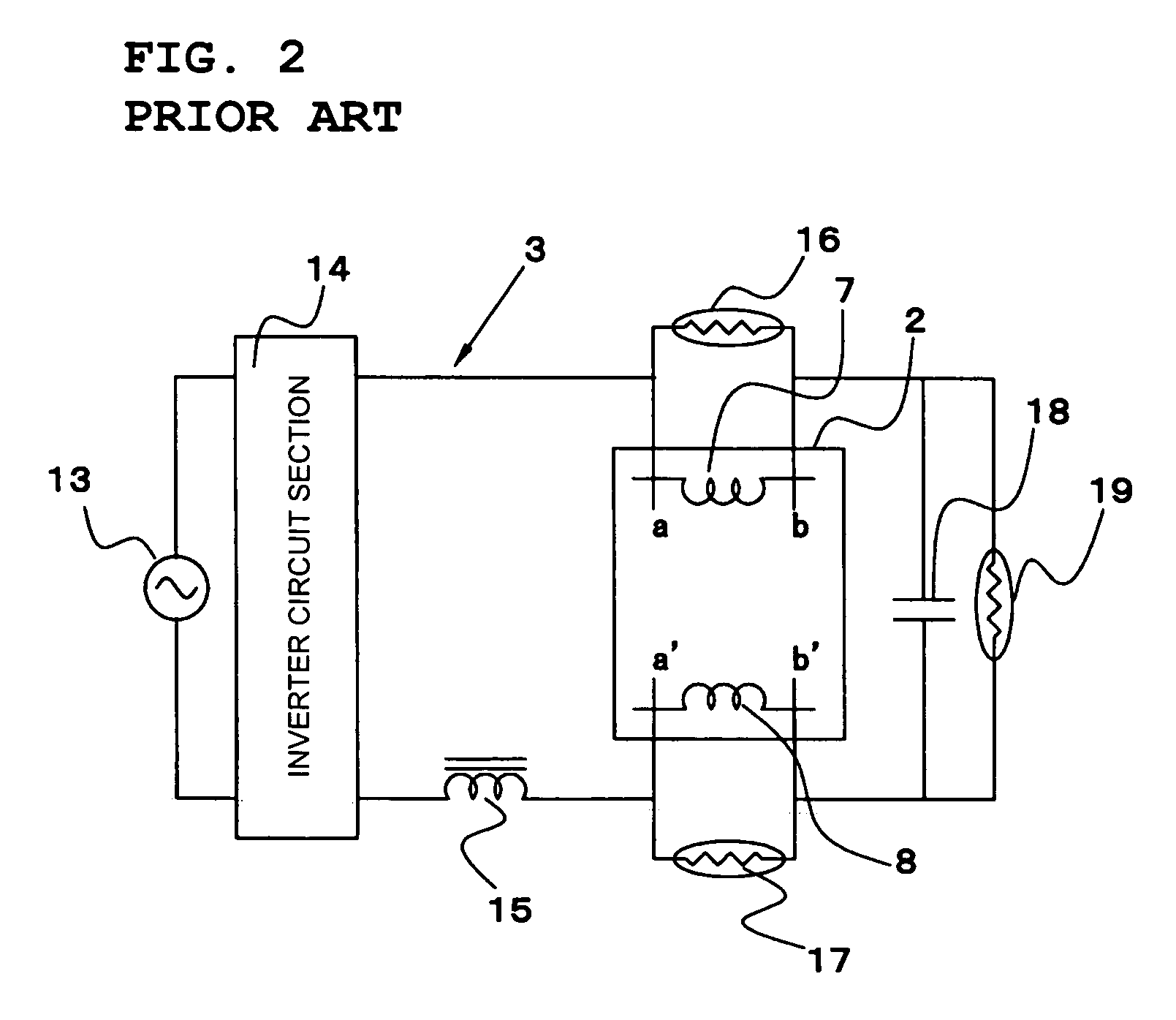
[0026]A description will also be given with reference to FIG. 2. The fluorescent light bulb 2 is provided with a pair of electrode filaments 7 and 8. Inside one of the tube end portions of the fluorescent light bulb 2, one of the ...


PUM


Abstract

A fluorescent lamp lighting device includes a fluorescent light bulb having an electrode filament and an electronic lighting circuit substrate for lighting the fluorescent light bulb, wherein a capacitor connected in parallel with the fluorescent light bulb, a positive characteristic thermistor connected in parallel with the capacitor, and a negative characteristic thermistor connected in parallel with the electrode filament are mounted on the electronic lighting circuit substrate, and wherein the negative characteristic thermistor, having a mounting surface, is mounted in such a manner that the mounting surface is in abutment with the electronic lighting circuit substrate. The positive characteristic thermistor and the negative characteristic thermistor are preferably mounted on mutually different mounting surfaces among the two mounting surfaces of the obverse and reverse surfaces of the electronic lighting circuit substrate.

Description

BACKGROUND OF THE INVENTION[0001]1. Field of the Invention[0002]The present invention relates to a fluorescent lamp lighting device for lighting a fluorescent light bulb by using an electronic lighting circuit.[0003]2. Description of the Related Art[0004]In recent years, as fluorescent lamp lighting devices, inverter-type electronic lighting devices have been commonly used in order to save energy. In particular, in fluorescent lamps incorporated in a lighting device, which is an energy-saving light source, in order to achieve higher-efficiency of a lamp, inverter-type electronic lighting circuits are becoming increasingly used.[0005]Japanese Unexamined Patent Application Publication No. 2001-357989 discloses a known fluorescent lamp. That is, ordinary fluorescent lamps are configured as shown in FIG. 3. A circuit substrate 20 on which an electronic lighting circuit 3 is formed is arranged between a base 6 arranged at the end portion of a resin case 5 and a fluorescent light bulb 2, ...

Claims


Application Information

Patent Timeline
Patent Type & Authority Patents(United States)
IPC IPC(8): H01J17/34H01J19/42H05B41/24H01J5/54H01J61/56H05B41/00H05B41/298
CPCH01J5/54H05B41/2988H01J61/56
Inventor YAMASHITA, YOSHIYUKIOHMURA, KINGOYOKOTA, ATSUOKAWASE, MASAHIKOTSUBAKI, SHUJI
Owner MURATA MFG CO LTD
Why Eureka
Try Eureka