A/D converter, battery pack, electronics device and method of voltage measurement

a voltage measurement and converter technology, applied in the field of an, can solve problems such as data loss under processing, and achieve the effects of simplifying the control program of the current measuring circuit, and increasing the dynamic range of the a/d converter

Inactive Publication Date: 2006-03-14
SOCIONEXT INC
View PDF7 Cites 18 Cited by
  • Summary
  • Abstract
  • Description
  • Claims
  • Application Information

AI Technical Summary

Benefits of technology

[0017]According to a preferred example of the mode of the present invention, a second storing circuit of the A / D converter, in which a measured value of the reference voltage is stored in advance, outputs the stored measured value as a digital value. For example, in a fabrication process of the A / D converter, the reference voltage is measured at a predetermined temperature, and the measured value is stored in the second storing circuit. The current measuring circuit can obtain the measured value of the reference voltage which corresponds to a voltage value of the reference voltage during A / D conversion. Therefore, the current measuring circuit corrects the digital value from the A / D converting circuit by using the digital value from the second storing circuit, so that the digital value accurately showing the output voltage of the amplifying circuit can be obtained, irrespective of accuracy of the reference voltage. As a result of this, the current measuring circuit corrects the digital value from the A / D converting circuit by using the digital value from the second storing circuit and thereafter adds the digital value from the first storing circuit thereto, thereby obtaining the digital value accurately showing the voltage difference between both ends of the resistor element (the current value of the current path).
[0018]According to a preferred example of the mode of the present invention, the bias circuit selects the bias voltage to be added to the second external input voltage out of a plurality of bias voltages according to the output voltage of the amplifying circuit. The first storing circuit stores measured values of the plurality of bias voltages in advance, selects the measured value of the bias voltage selected by said bias circuit, and outputs it as the digital value. By providing the plurality of bias voltages, it is possible to further increase the dynamic range of the A / D converter.
[0019]According to a preferred example of the mode of the present invention, a measurement voltage generating circuit of the A / D converter generates a measurement voltage for measuring temperature which fluctuates in response to ambient temperature around the A / D converter. A selecting circuit of the A / D converter selects and outputs the measurement voltage and thereafter the output voltage of the amplifying circuit as an input voltage of the A / D converting circuit. A holding circuit of the A / D converter holds the digital value which is output from the A / D converting circuit in association with the selection of the measurement voltage by the selecting circuit. The first storing circuit stores the measured values of the plurality of bias voltages at every ambient temperature around the A / D converter in advance, selects the measured value corresponding to the digital value held by the holding circuit, out of the measured values of the bias voltages selected by the bias circuit, and outputs it as a digital value. Accordingly, the digital value from the first storing circuit shows the measured value of the bias voltage corresponding to the current ambient temperature around the A / D converter. Therefore, the current measuring circuit can obtain the digital value accurately showing the voltage difference between both ends of the resistor element (the current value of the current path) at all times, even when the bias voltage fluctuates according to fluctuation of the ambient temperature around the A / D converter.
[0020]According to a preferred example of the mode of the present invention, a second storing circuit, in which the measured values of the reference voltage at every ambient temperature around the A / D converter are stored in advance, selects the measured value corresponding to the digital value held by the holding circuit, and outputs it as a digital value. Accordingly, the digital value from the second storing circuit shows the measured value of the reference voltage corresponding to the current ambient temperature around the A / D converter. Therefore, the current measuring circuit can obtain the digital value accurately showing the input voltage of the A / D converting circuit (the output voltage of the amplifying circuit) at all times, even when the reference voltage fluctuates according to the ambient temperature around the A / D converter.
[0021]According to a preferred example of the mode of the present invention, a third storing circuit of the A / D converter, in which a standard value of the reference voltage is stored in advance, outputs the stored standard value as a digital value. A correcting circuit of the A / D converter corrects the digital value from the A / D converting circuit to be a digital value which is based on the standard value of the reference voltage, in accordance with the digital values from the second and third storing circuits, and outputs it. An adding circuit of the A / D converter adds the digital value from the correcting circuit and the digital value from the first storing circuit, and outputs the added result. Thereby, it is possible to eliminate the need for the operation of the current measuring circuit correcting the digital value from the A / D converting circuit by using the digital value from the second storing circuit, and adding the corrected digital value and the digital value from the first storing circuit. Therefore, it is possible to simplify a control program of the current measuring circuit which is constituted with a microcontroller or the like.
[0022]According to a preferred example of the mode of the present invention, an adding circuit of the A / D converter adds the digital value from the A / D converting circuit and the digital value from the first storing circuit, and outputs the added result. Thereby, it is possible to eliminate the need for the operation of the current measuring circuit adding the digital value from the A / D converting circuit and the digital value from the first storing circuit. Therefore, it is possible to simplify the control program of the current measuring circuit which is constituted with the microcontroller or the like.

Problems solved by technology

Meanwhile, when the portable electronics device is operated by a battery, there is the possibility of losing data under processing if a battery remaining capacity is used up and the power supply is interrupted during its operation.

Method used


Image

  • A/D converter, battery pack, electronics device and method of voltage measurement
  • A/D converter, battery pack, electronics device and method of voltage measurement
  • A/D converter, battery pack, electronics device and method of voltage measurement

Examples


Embodiment Construction

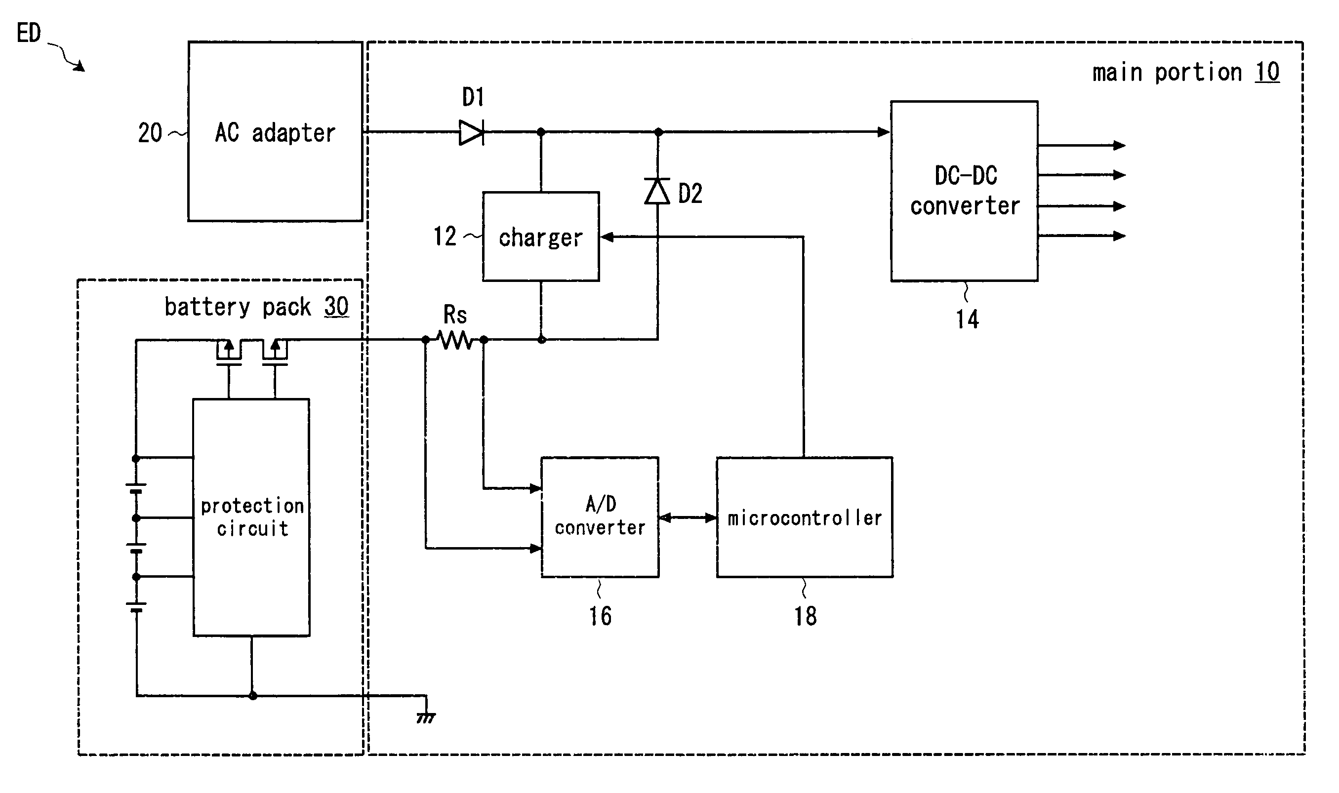
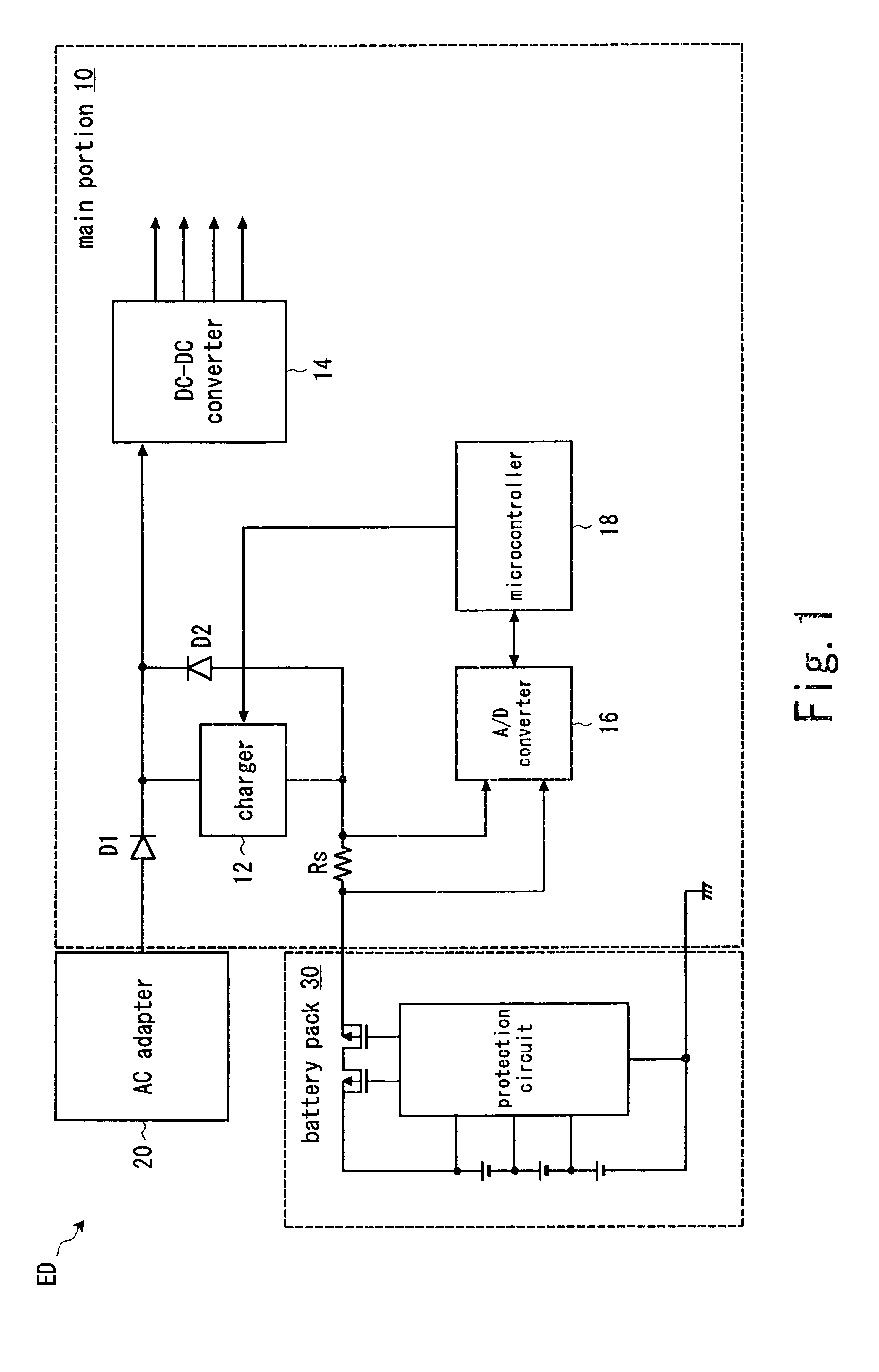
[0035]Hereinafter, preferred embodiments of the present invention will be explained with reference to the drawings. FIG. 1 shows a first embodiment of the present invention. A portable electronics device (a notebook personal computer, for example) ED includes a main portion 10, an AC adapter 20, and a battery pack 30. The main portion 10 includes a charger 12, a DC—DC converter 14, an A / D converter 16, a microcontroller 18, a resistor Rs, and diodes D1 and D2. The diode D1 is a backflow preventing circuit which prevents power supplied from the battery pack 30 from being supplied to the AC adapter 20 side. The diode D2 is a backflow preventing circuit which prevents power supplied from the AC adapter 20 from being supplied to the battery back 30 side.

[0036]The charger 12 follows an instruction from the microcontroller 18 to charge the battery pack 30 using the power supplied from the AC adapter 20. The DC—DC converter 14 uses the power supplied from the AC adapter 20 or the battery p...


PUM

PropertyMeasurementUnit
leak currentaaaaaaaaaa
currentaaaaaaaaaa
currentaaaaaaaaaa

Abstract

An amplifying circuit amplifies and outputs voltage difference between first external input voltage and voltage corresponding to second external input voltage. An A/D converting circuit converts the output voltage of the amplifying circuit into a digital value by comparing it with reference voltage, and outputs it. A bias circuit selects the second external input voltage or voltage obtained by adding bias voltage to the second external input voltage, according to the output voltage of the amplifying circuit, and outputs it as the voltage corresponding to second external input voltage. A first storing circuit prestores a measured value of the bias voltage, and outputs the stored value as a digital value whose bit number is greater than that of the digital value from the A/D converting circuit, when the voltage corresponding to second external input voltage is the voltage obtained by adding the bias voltage to the second external input voltage.

Description

CROSS-REFERENCE TO RELATED APPLICATIONS[0001]This application is based upon and claims the benefit of priority from Japanese Patent Application No. 2004-305954, filed on Oct. 20, 2004, the entire contents of which are incorporated herein by reference.BACKGROUND OF THE INVENTION[0002]1. Field of the Invention[0003]The present invention relates to an A / D converter, a battery pack, an electronics device and a method of voltage measurement and, more particularly, to technology which uses the A / D converter for measuring a voltage difference between both ends of a resistor element inserted in a current path in series, with the aim of current measurement.[0004]2. Description of the Related Art[0005]When a portable electronics device (a notebook personal computer, an electronic notebook or the like) is operated by a commercial power supply via an AC adapter or the like, the power supply is not interrupted during its operation. Meanwhile, when the portable electronics device is operated by a...

Claims


Application Information

Patent Timeline
Patent Type & Authority Patents(United States)
IPC IPC(8): H03M1/12
CPCH03M1/186H01M10/42Y02E60/10A61L9/205B01D53/346B01D53/56B01D53/8628B01D53/88B01D2255/802B01J35/004H05H1/24
Inventor ARIMURA, KAZUYOSHIHAYAKAWA, ATSUSHIOGAWA, HIDEKIYO
Owner SOCIONEXT INC
Why Eureka
Try Eureka