Fluid coupling

Inactive Publication Date: 2006-03-21
EBARA CORP
View PDF13 Cites 1 Cited by
  • Summary
  • Abstract
  • Description
  • Claims
  • Application Information

AI Technical Summary

Benefits of technology

[0007]It is therefore an object of the present invention to provide a fluid coupling which has a clutch mechanism between a drive shaft side and a driven shaft side and can improve a power tr

Problems solved by technology

This slippage cannot be avoid d when the rotational speed on the load side is controlled by the fluid c

Method used


Image

  • Fluid coupling
  • Fluid coupling
  • Fluid coupling

Examples


first embodiment

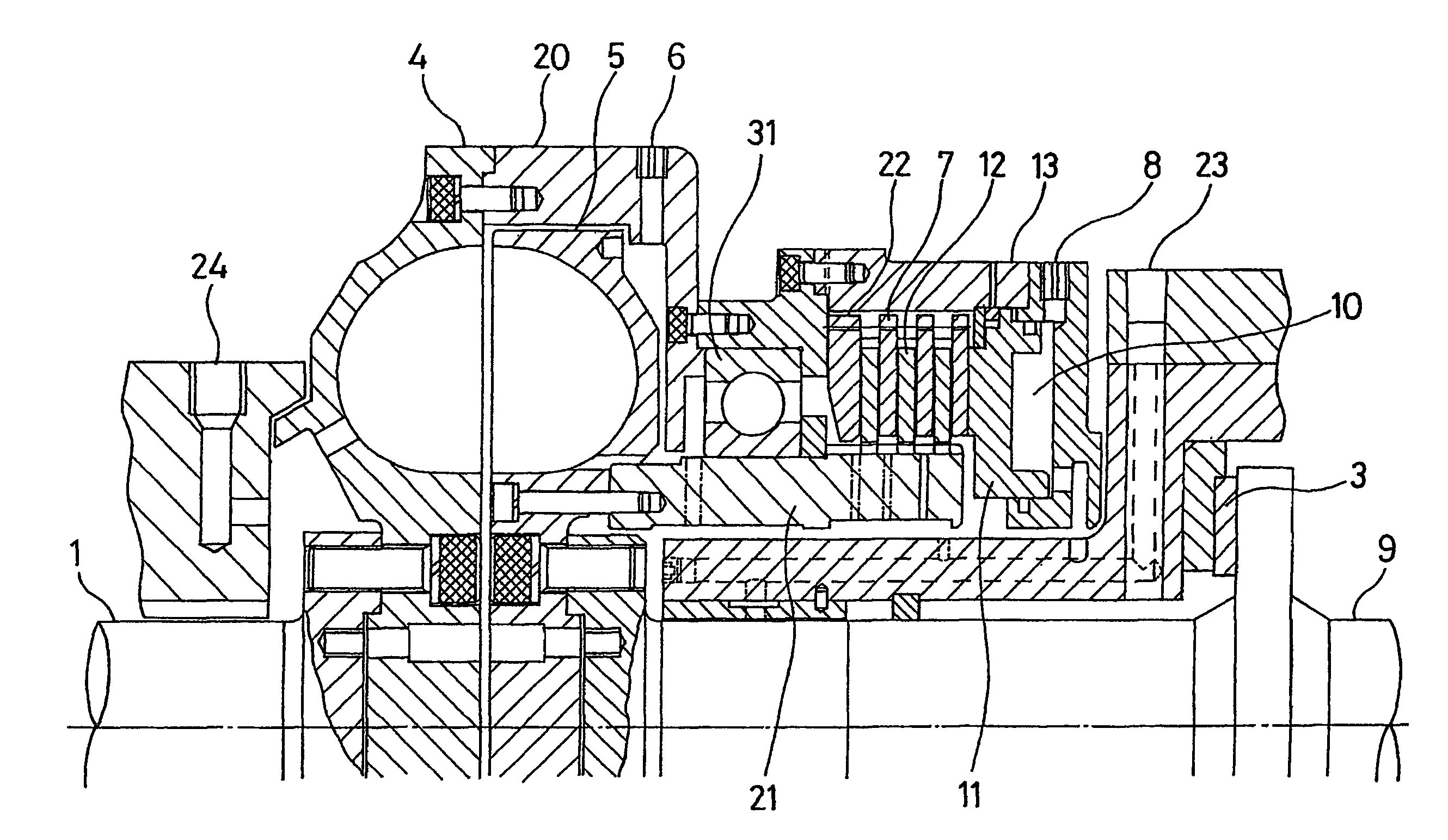
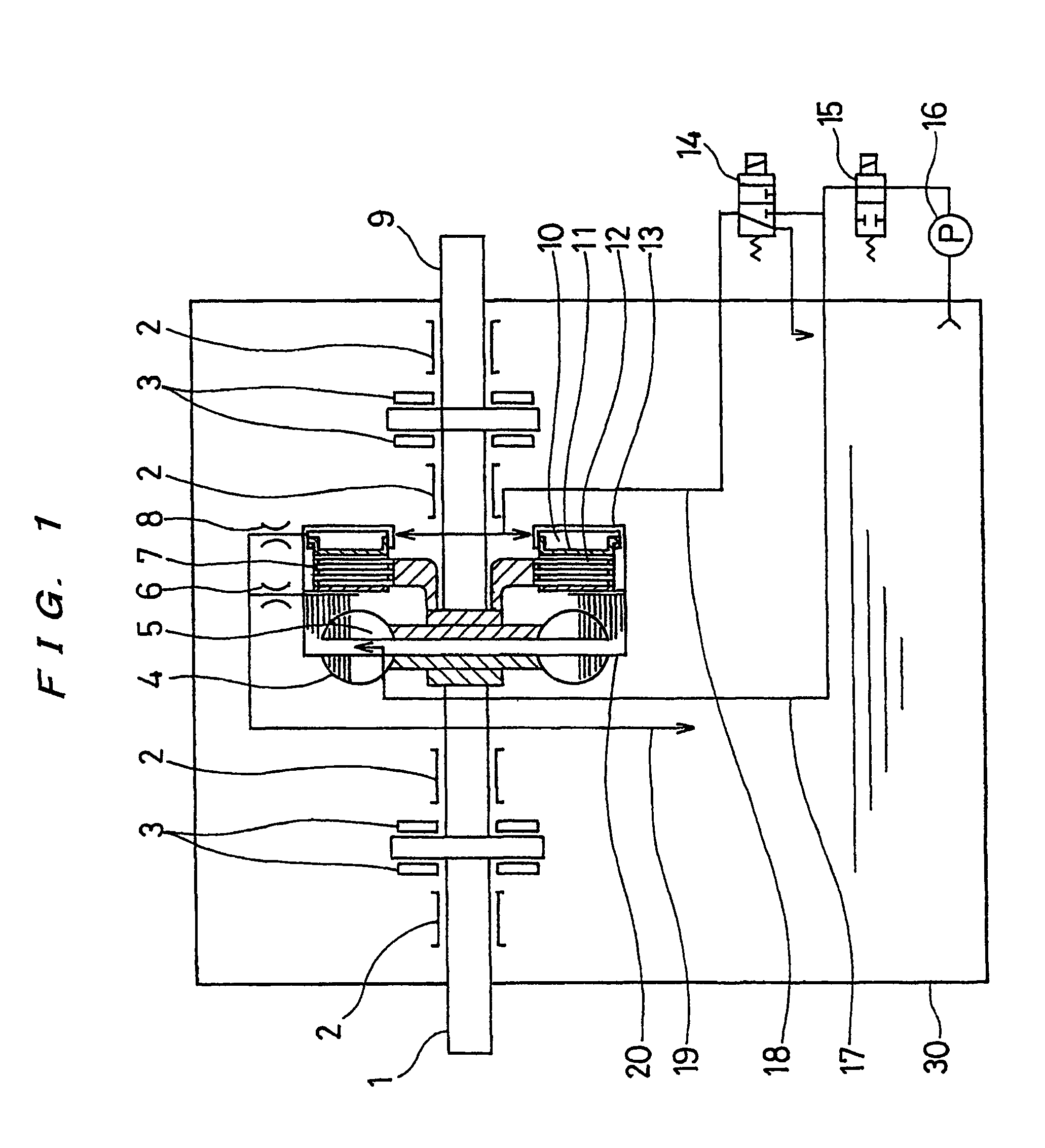
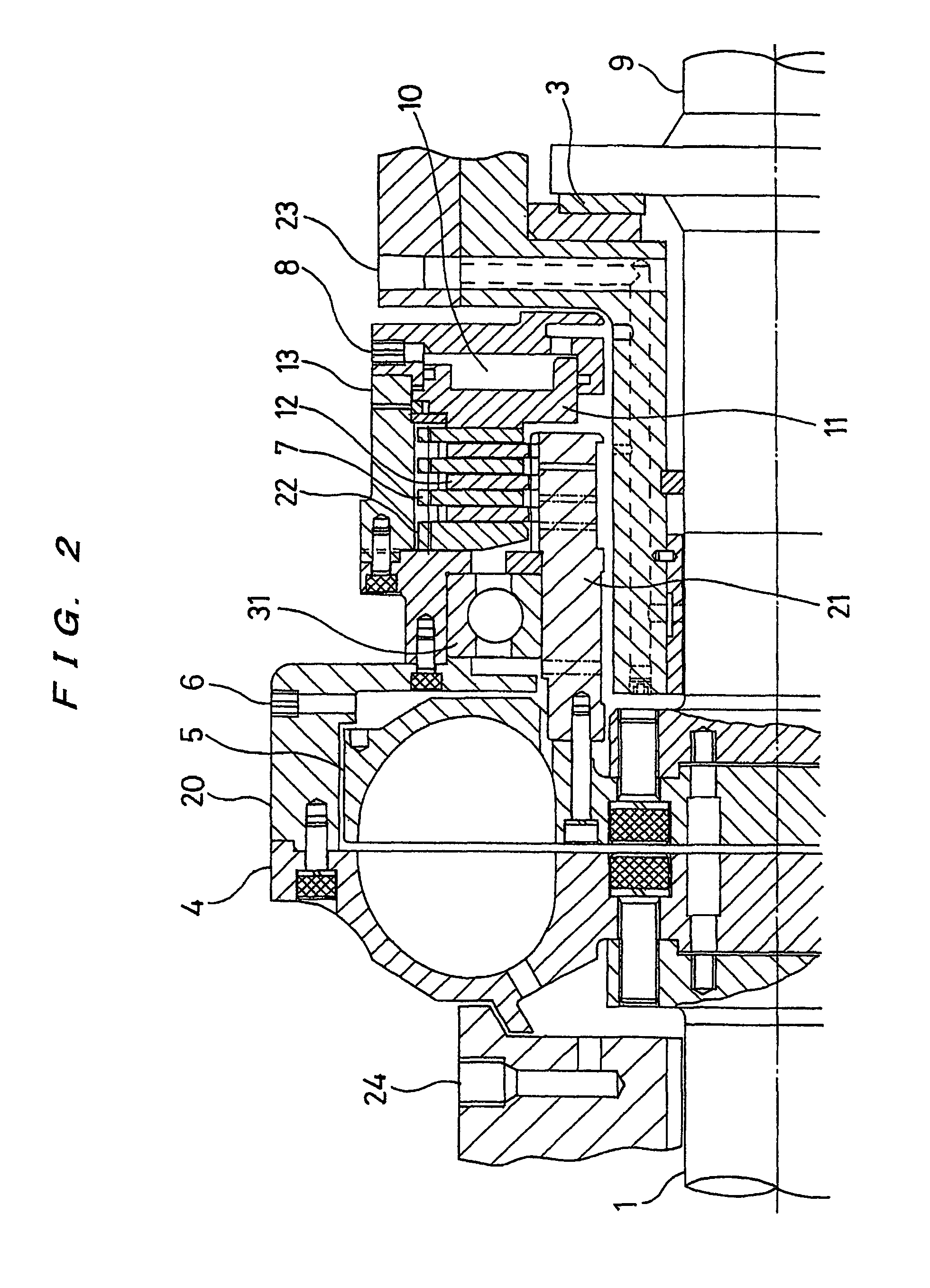
[0021]A fluid coupling according to the present invention will be described with reference to FIGS. 1 and 2.

[0022]The fluid coupling of the present invention has a multiple disc clutch between a drive shaft side and a driven shaft side. When a pressurized fluid such as pressurized oil is supplied to a hydraulic cylinder, the multiple disc clutch is pressed against each other, thus connecting the clutch. In this case, as a method for producing a pressurized fluid, there are a method in which a pressure produced by a centrifugal force applied to oil which rotates together with a drive-side rotating body is utilized, a method in which an oil pressure produced by a hydraulic pump which is mechanically connected to a drive shaft is utilized, and a method in which an oil pressure produced by a hydraulic pump which is driven by an electric motor is utilized. The fluid coupling shown in FIGS. 1 and 2 utilizes a pressure produced by a centrifugal force applied to oil which rotates together w...

second embodiment

[0034]FIGS. 3 through 5 are views showing a fluid coupling according to the present invention. FIG. 3 is a schematic view of the fluid coupling having a multiple disc clutch therein, FIG. 4 is a cross-sectional view of a power transmitting section of the fluid coupling, and FIG. 5 is a cross-sectional view of the multiple disc clutch. In the fluid coupling shown in FIGS. 3 through 5, there are provided a device for limiting a stroke of the piston for pressing the clutch plates of the multiple disc clutch in the fluid coupling, and a device for detecting an amount of wear of the friction plates of the multiple disc clutch.

[0035]In FIGS. 3 through 5, the parts or elements which are identical to those shown in FIGS. 1 and 2 are denoted by the same reference numerals.

[0036]The structure of the fluid coupling shown in FIG. 3 is almost the same as the fluid coupling shown in FIG. 1. As shown in FIG. 3, a detecting apparatus 32 for detecting a rotational speed of a drive shaft is attached ...

third embodiment

[0044]FIGS. 6 and 7 are views showing a fluid coupling according to the present invention. FIG. 6 is a schematic view of the fluid coupling having a multiple disc clutch therein, and FIG. 7 is a cross-sectional view of a power transmitting section of the fluid coupling.

[0045]In the embodiment shown in FIGS. 6 and 7, at a certain location of the supply pipe 17, there is provided a bypass passage Bp, having an orifice 41 for setting a minimum amount of the working oil, which is bypassed from a main passage which has the fluid-coupling solenoid controlled valve 15 (see FIG. 6). Further, at the location inside of the discharge nozzle 6, there is provided a dam 42 which projects radially inwardly from the inner wall surface of the fluid-coupling housing 20 (see FIG. 7). A minimum rotational speed of the fluid coupling can be set by the dam 42. Specifically, the minimum rotational speed of the fluid coupling can be adjusted by changing the height h of the dam 42 from the inner wall surfac...


PUM


Abstract

A fluid coupling transmits power from a drive side to a driven side by utilizing kinetic energy of fluid such as oil. The fluid coupling comprises a pump impeller (4) provided on a drive shaft (1), a turbine impeller (5) provided on a driven shaft (9), a housing (20) fixed to the pump impeller (4) and surrounding the turbine impeller, and a multiple disc clutch provided between a drive shaft side and a driven shaft side. The multiple disc clutch is operated to couple the drive shaft (1) and the driven shaft (9) mechanically so that the drive shaft and the driven shaft are rotated at the same rotational speed. Thus, the fluid coupling can improve a power transmitting efficiency because of no slip between the rotational speed of the drive shaft and the rotational speed of the driven shaft.

Description

TECHNICAL FIELD[0001]The present invention relates to a fluid coupling for transmitting power from a drive side to a driven side by utilizing kinetic energy of fluid such as oil, and more particularly to a fluid coupling which has a clutch mechanism for mechanically coupling a drive shaft coupled to a prime mover and a driven shaft coupled to a driven machine and can improve a power transmitting efficiency by equalizing the rotational speed of the driven shaft to the rotational speed of the drive shaft without any slip loss.BACKGROUND ART[0002]There has been known a fluid coupling which has a pump impeller connected to a drive shaft and a turbine impeller connected to a driven shaft and transmits power from the drive shaft to the driven shaft via fluid filled in a casing.[0003]In case of performing a rotational speed control by means of a fluid coupling, the rotational speed on a load side can be steplessly changed from a minimum rotational speed to a maximum rotational speed by usi...

Claims


Application Information

Patent Timeline
IPC IPC(8): F16H45/02F16D25/0638F16H61/14
CPCF16H45/02F16H61/14F16H2045/0284
Inventor KIMURA, KATSUMIHATTORI, KAZUOOGATA, HIROSHIKATAYA, YOSHINORISUGIYAMA, KAZUHIKO
Owner EBARA CORP
Why Eureka
Try Eureka