Pumping apparatus for slurry polymerization in loop reactors

Active Publication Date: 2006-03-21
FLOWSERVE MANAGEMENT CO +1
View PDF9 Cites 58 Cited by
  • Summary
  • Abstract
  • Description
  • Claims
  • Application Information

AI Technical Summary

Benefits of technology

[0017]In any of these loop slurry polymerization processes, one may minimize the clearance between at least one impeller and a portion of the loop reactor housing the impeller. In the improved processes, the slurry may have has a desired minimum concentration of the solid po

Problems solved by technology

As the volume of the reactor and the solids concentration of th

Method used


Image

  • Pumping apparatus for slurry polymerization in loop reactors
  • Pumping apparatus for slurry polymerization in loop reactors
  • Pumping apparatus for slurry polymerization in loop reactors

Examples


Embodiment Construction

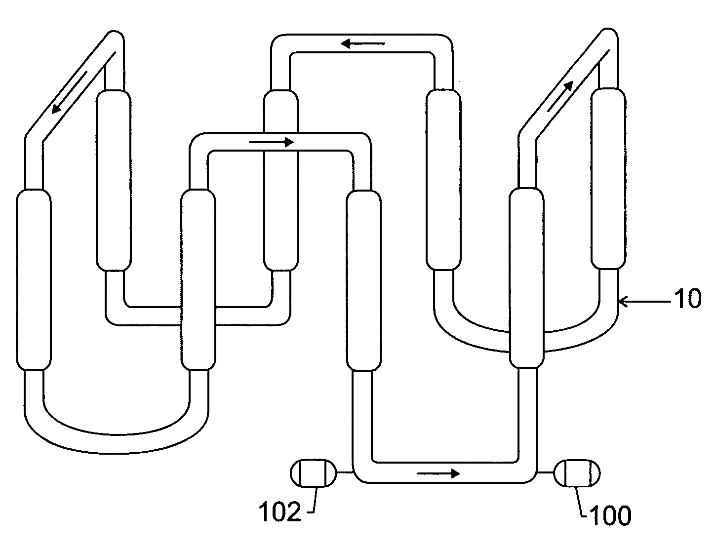
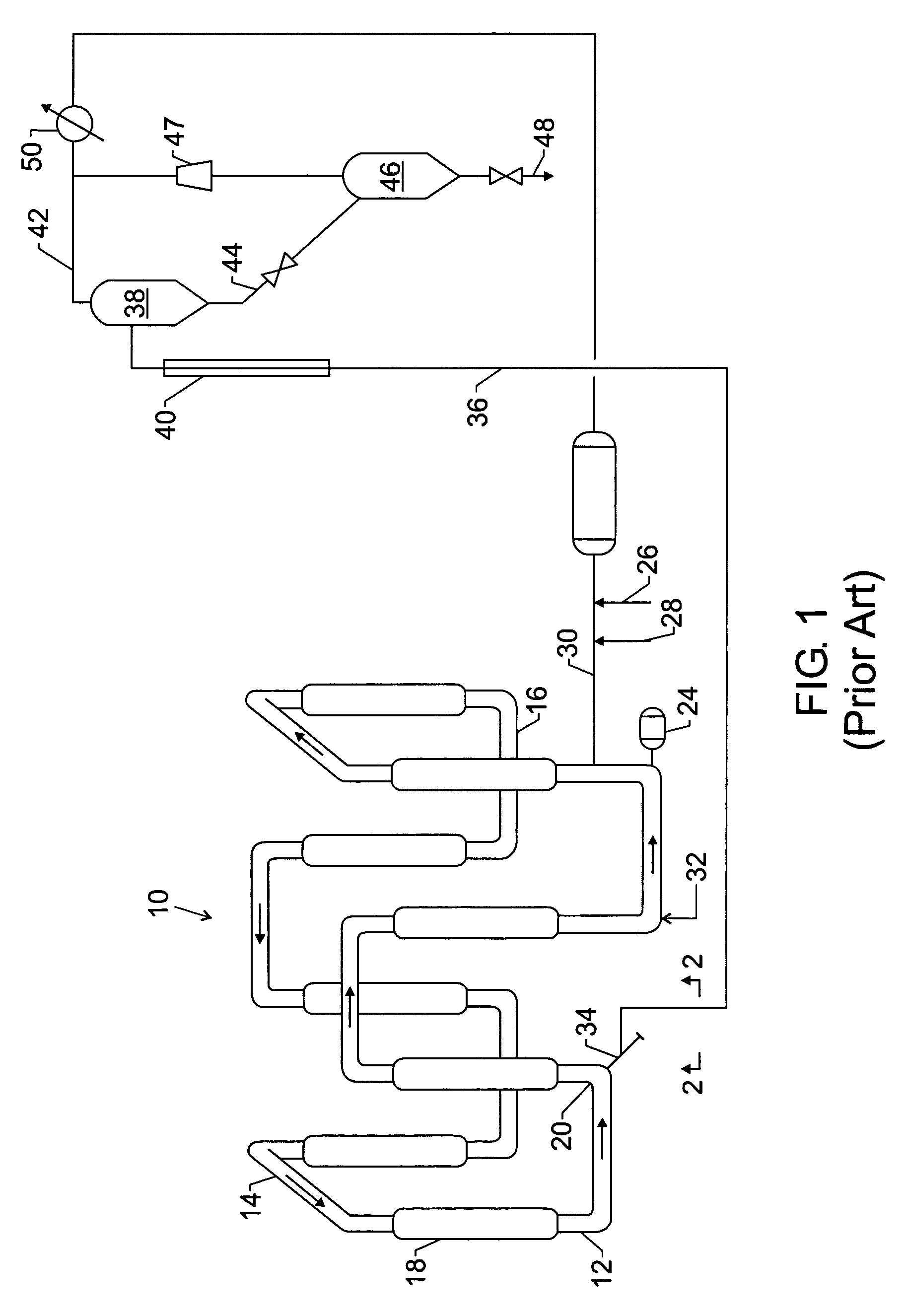
[0025]The present process and apparatus are applicable to any loop reaction zone, which comprises a slurry of polymer solids in a liquid medium, including slurries employed in olefin polymerization processes. In particular, the present process and apparatus are applied to large-volume loop reactors in which a fluid slurry having a high solids concentration is circulated.

[0026]As used herein, the term “slurry” means a composition in which solids and liquid are present in separate phases. The term “fluid slurry” means the slurry comprising polymer solids and liquid medium circulating in a loop reaction zone. The solids may include catalyst and a polymerized olefin, such as polyethylene. The liquid medium may include an inert diluent, such as isobutane, with dissolved monomer, comonomer, molecular weight control agents, such as hydrogen, antistatic agents, antifouling agents, scavengers, and other process additives. Alternatively, the liquid medium may be made up primarily of the unrea...


PUM

PropertyMeasurementUnit
Angleaaaaaaaaaa
Volumeaaaaaaaaaa
Volumeaaaaaaaaaa

Abstract

An olefin polymerization process and apparatus wherein a fluid slurry comprising monomer, diluent and catalyst is circulated in a continuous loop reactor by two or more pumps. The process and apparatus allow operating the reaction at significantly higher solids content in the circulating fluid slurry. In a preferred embodiment, the fluid slurry is circulated by two impellers arranged so that the downstream impeller benefits from the rotational energy imparted by the upstream impeller. An olefin polymerization process operating at higher reactor solids by virtue of more aggressive circulation has improved efficiencies, particularly in larger-volume reactors.

Description

RELATED APPLICATIONS[0001]This application claims the benefit under 35 U.S.C. § 119(e) of U.S. Provisional Application No. 60 / 411,612 (“the '612 application”) filed on Sep. 17, 2002. The '612 application is incorporated by reference herein.FIELD OF THE INVENTION[0002]This invention relates to slurry polymerization in a liquid medium. More particularly, the invention relates to improved pumping apparatus and processes for a large-volume loop reactor used for slurry polymerization.BACKGROUND OF THE INVENTION[0003]Polyolefins such as polyethylene and polypropylene may be prepared by particle form polymerization, also referred to as slurry polymerization. In this technique, feed materials such as monomer and catalyst are fed to a loop reactor, and a product slurry containing solid polyolefin particles in a liquid medium is taken off or withdrawn from the reactor.[0004]In a loop polymerization operation, a fluid slurry is circulated around the loop reactor using one or more pumps, typica...

Claims


Application Information

Patent Timeline
IPC IPC(8): C08F2/01B01J8/08B01J8/10B01J8/20B01J8/22B01J19/00B01J19/18C08F2/00C08F6/00C08F10/00C08F110/06C08F210/16C08G85/00F04D
CPCB01J8/0015C08F2/01B01J8/20B01J8/226B01J8/382B01J19/006B01J19/0066B01J19/1837B01J19/1875C08F6/003C08F10/00B01J8/005C08L23/10C08F2/14B01J2219/00094B01J2219/00114B01J2219/00189B01J2219/00777C08F10/02C08F10/06C08F110/06C08F210/16C08F210/14C08F210/08
Inventor HOTTOVY, JOHN D.ZELLERS, DALE A.FRANKLIN, ROBERT K.
Owner FLOWSERVE MANAGEMENT CO
Why Eureka
Try Eureka