
Engine operated machine

Active Publication Date: 2006-03-21
HONDA MOTOR CO LTD
View PDF21 Cites 10 Cited by
  • Summary
  • Abstract
  • Description
  • Claims
  • Application Information

AI Technical Summary

Benefits of technology

[0006]An object of the present invention is to provide an engine operated machine which can suitably change a driving force in correspondence to a rapid load change.
[0010]According to the second aspect, in the first region, since the electric motor is in an idling state in which the electric motor functions neither as a power generator nor an electric motor, all of the engine output can be supplied to the load in this first region. Further, by providing this first area, it is possible to inhibit the electric motor from being frequently changed between a power generator operation and an electric motor operation.

Problems solved by technology

However, since it is judged based on the exhaust temperature that the large driving force is actually required, it is hard to execute such an operation as to supplement only a necessary driving force in correspondence to a rapid load change.

Method used


Image

  • Engine operated machine
  • Engine operated machine
  • Engine operated machine

Examples


Embodiment Construction

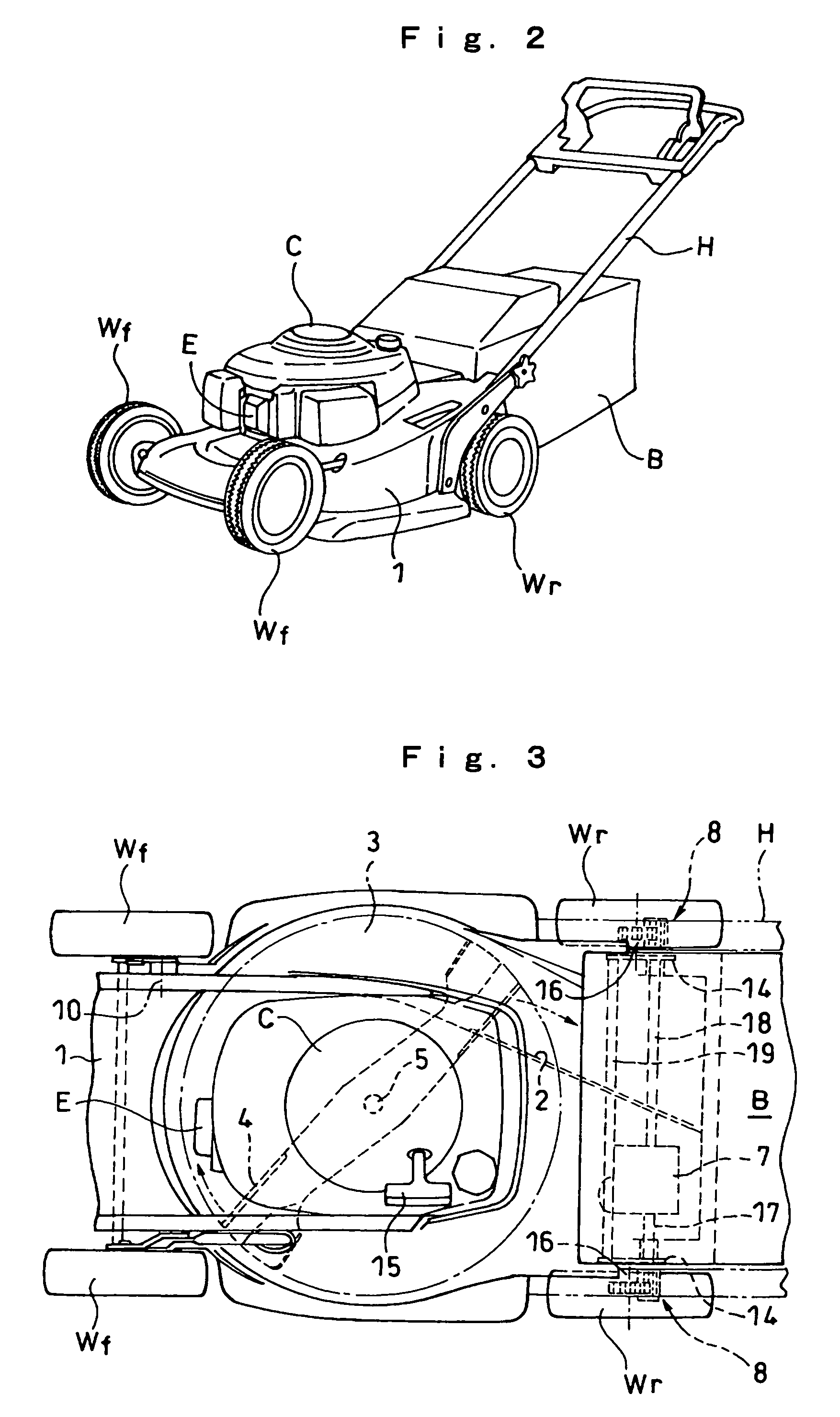
[0024]A description will be given in detail below of an embodiment according to the present invention with reference to the accompanying drawings. FIG. 2 is a perspective view of an entire of a lawn mower corresponding to an engine operated machine according to an embodiment of the present invention, and FIG. 3 is a plan view of a main portion of the lawn mower. In FIG. 2, a pair of front wheels Wf and Wf is suspended to a front portion of a cutter housing 1 in the lawn mower, and a pair of rear wheels Wr and Wr is suspended to a rear portion of the cutter housing. An engine E in which an output shaft or a crankshaft is vertically provided is mounted in a center portion of the cutter housing 1, and an engine cover C is put on an upper protruding portion of the engine E. An operation handle H extending so as to rearward ascend toward a rear side is provided in both sides of a rear portion of the cutter housing 1, and a grass bag B for receiving mown lawn grasses is provided in the re...


PUM


Abstract

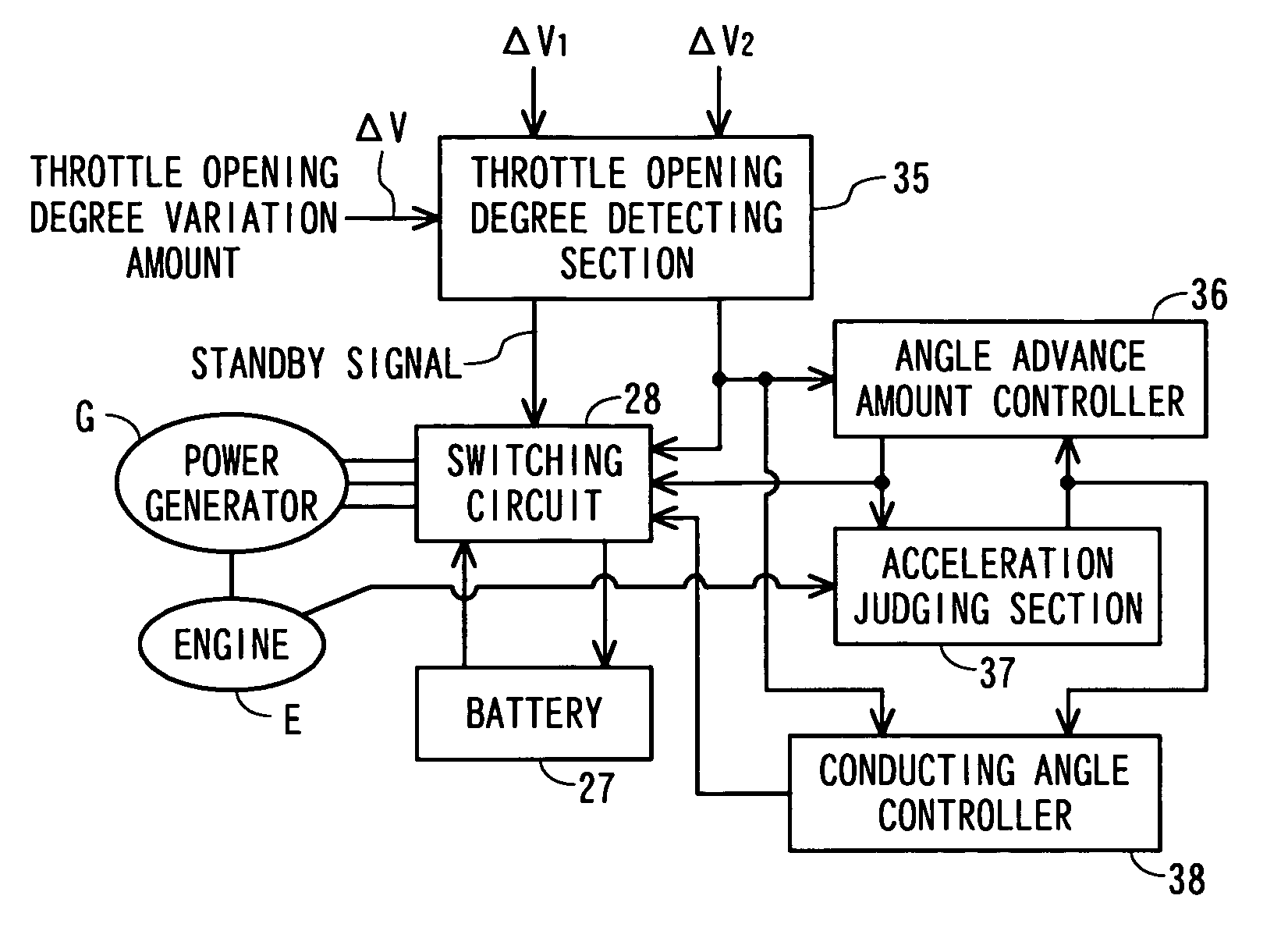
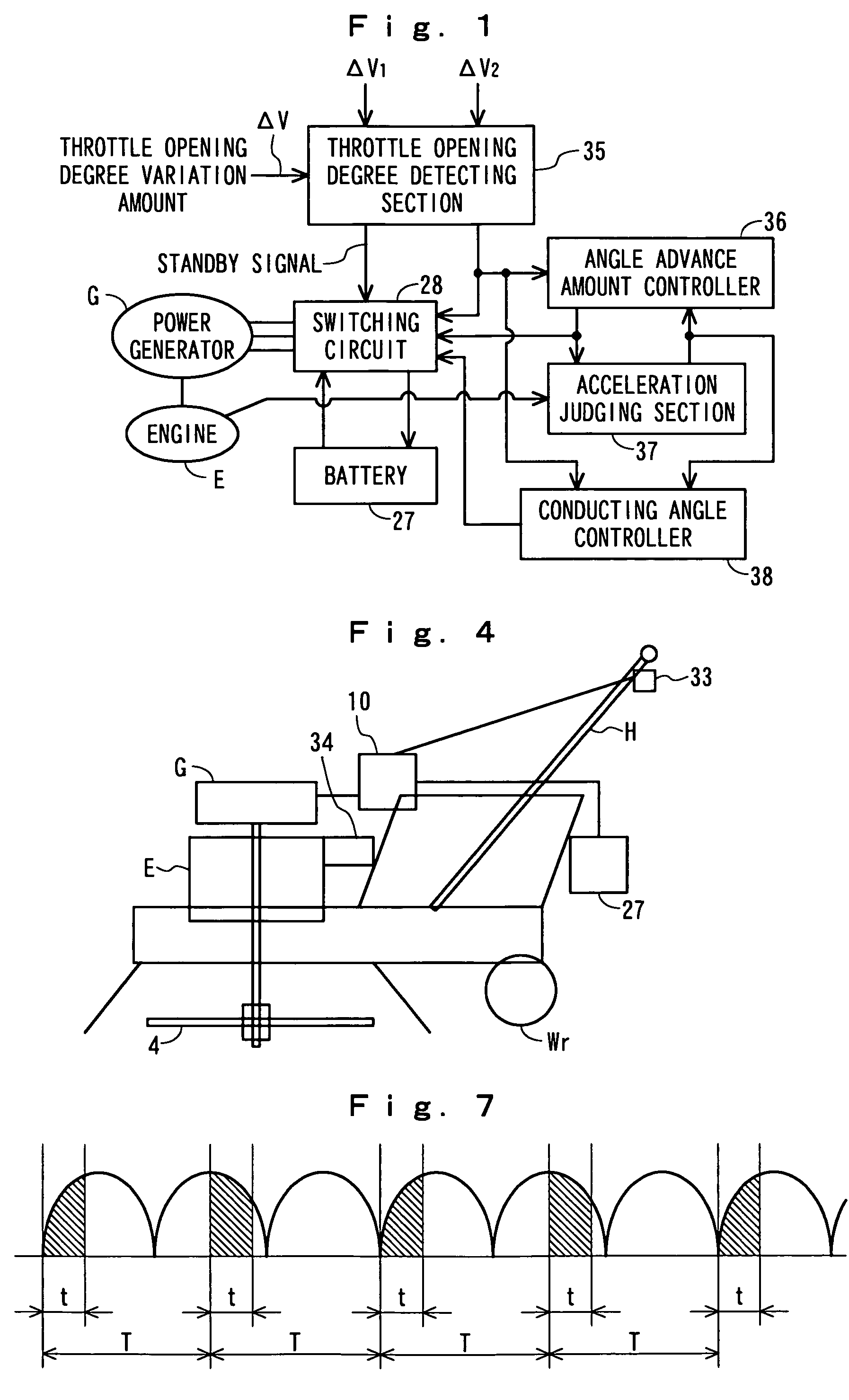
The invention makes an output sharing of an engine and an electric motor proper so as to suitably drive a load. When a throttle opening degree variation amount ΔV is within a ΔV1, an engine E can drive a power generator G at a rated revolution speed. A switching circuit 28 is switched in such a manner as to charge a battery 27 by a generated power. When the opening degree variation amount ΔV becomes larger than the ΔV1, a power assist of operating the power generator G as the electric motor is set to be standby. When the opening degree variation amount ΔV is more than ΔV2 (>ΔV1), the power assist is started. In the power assist, an angle advance amount is increased. When acceleration is insufficient, it is possible to further increase a conduction angle in stages.

Description

BACKGROUND OF THE INVENTION[0001]1. Field of the Invention[0002]The present invention relates to an engine operated machine, and more particular to an engine operated machine in which an electric motor that is also operated as a power generator is connected to an output shaft of an engine.[0003]2. Description of the Related Art[0004]An agricultural working machine, called as a hybrid powered engine operated machine structured such that both an engine power and an electric motor power can be used has been known. For example, in Japanese Patent Application Laid-Open No. 2001-161114, there is proposed an engine drive passenger farming machine in which in the case that a load of the farming machine is small, a surplus energy that is generated by an engine driven generator is accumulated, and in the case that the load is large, an electric motor is driven by the electric power. In the passenger farming machine, it is judged that the load is large, in the case that an exhaust temperature ...

Claims


Application Information

Patent Timeline
IPC IPC(8): H02P7/32A01D34/68A01D34/78B60K6/48H02K21/22H02P3/00H02P9/00H02P9/04
CPCA01D34/78H02K21/22A01D69/025H02P9/00H02P6/18
Inventor WAKITANI, TSUTOMUKAWAKAMI, TOSHIAKIINAGAWA, TOSHINORISHINOGI, YOSHIHISA
Owner HONDA MOTOR CO LTD
Learn More