Circuit for operating an electric motor

a technology for electric motors and circuits, applied in the direction of motor/generator/converter stoppers, dynamo-electric converter control, instruments, etc., can solve the problem that electric motors may no longer be able to produce the necessary starting torqu

Inactive Publication Date: 2006-03-21
ROBERT BOSCH GMBH
View PDF19 Cites 4 Cited by
  • Summary
  • Abstract
  • Description
  • Claims
  • Application Information

AI Technical Summary

Benefits of technology

[0008]An advantageous embodiment of the circuit configuration according to the present invention provides that a change in the sign of the difference between the setpoint and the actual value supplies a third switch signal, which causes the feed of current to the electric motor to be cut off. This measure makes a simple implementation of the regulator possible, making it possible to stop the feed of current to the electric motor if the system deviation reaches zero.
[0009]An advantageous embodiment of the circuit configuration according to the present invention provides that the timer is designed as a retriggerable timer. The second switch signal, which the detection system supplies after a change in the position setpoint, starts the timer again independently of a time that may

Problems solved by technology

If the operating voltage of the electric motor drops, it is possible that the electric motor may no longer be able to pro

Method used


Image

  • Circuit for operating an electric motor
  • Circuit for operating an electric motor

Examples


Embodiment Construction

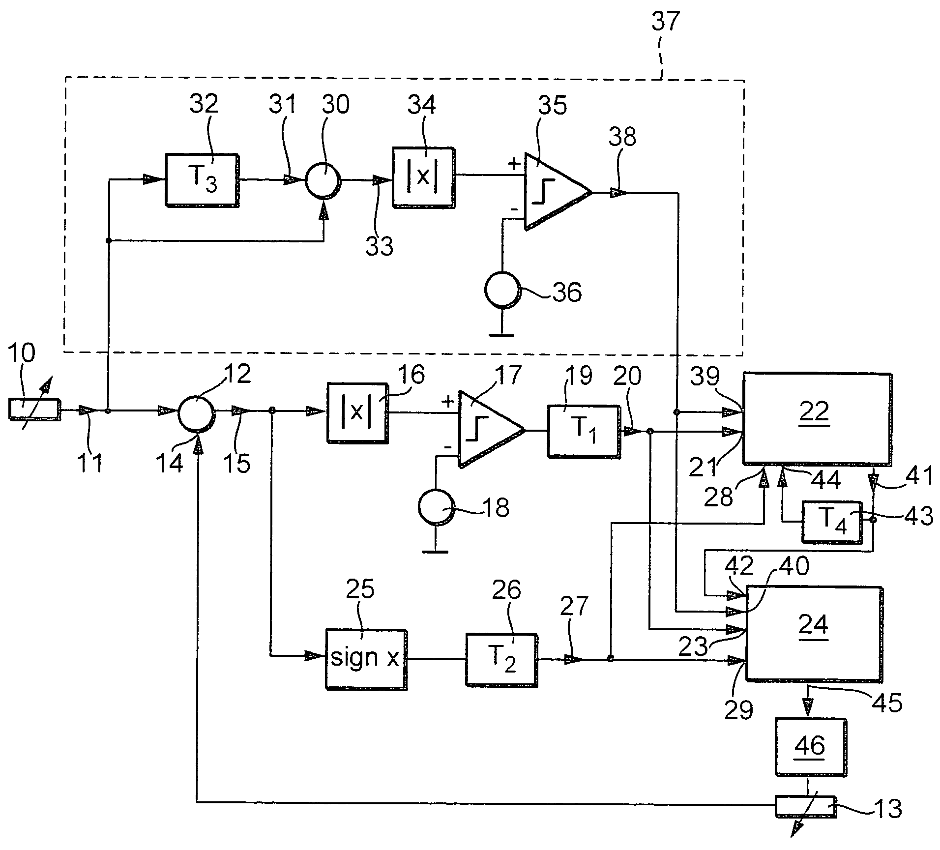
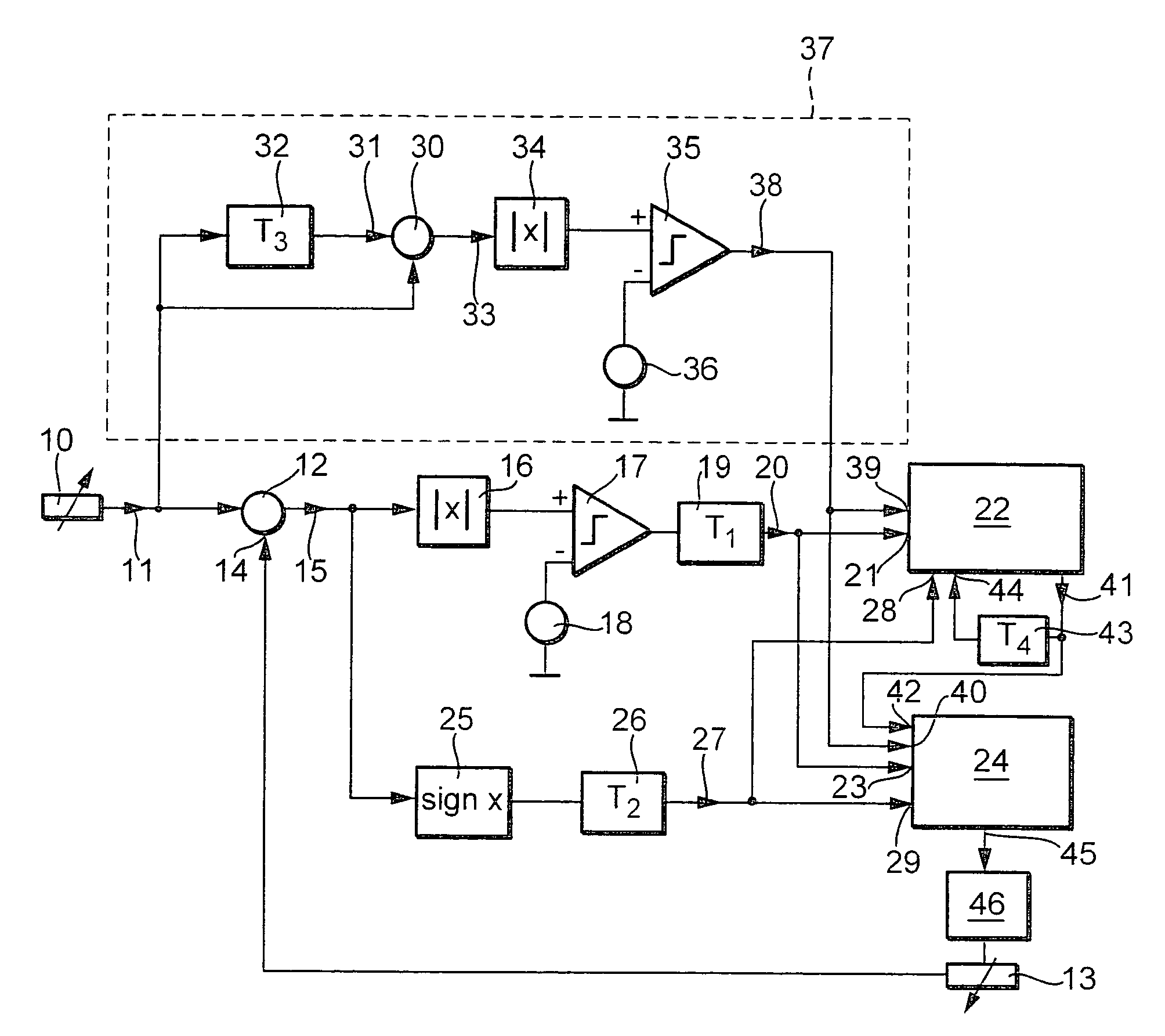
[0014]According to the FIGURE, a setpoint generator 10 outputs a setpoint signal 11 to a subtractor 12, which determines the difference between setpoint signal 11 and an actual value signal 14 supplied by an actual value sensor 13 and supplies it as first differential signal 15.

[0015]After passing through a first absolute value generator 16, first differential signal 15 is compared with a first hysteresis value 18 in a first comparator 17.

[0016]After the passage of a first time delay TI 19, first comparator 17 supplies a first switch signal 20, which is fed as a start signal to a first start input 21 of a timer 22 and to a first start input 23 of a motor control 24.

[0017]Further, after passing through a zero crossing detector 25 and a second time delay T226, differential signal 15 reaches a first reset input 28 of timer 22 and a first cutoff input 29 of motor control 24 as a cutoff signal 27.

[0018]Setpoint signal 11 further reaches a second subtractor 30, which is further fed a dela...


PUM


Abstract

A circuit configuration for operating an electric motor is described, the circuit configuration containing a timer. As a function of a first differential signal between a setpoint signal and an actual value signal, a regulator supplies a first switch signal for feeding current to the electric motor. Simultaneously, the timer is started which limits the current feed signal to a specified maximum time. A detection system detects a change in the setpoint signal and thereupon outputs a second switch signal that also starts the timer and is able to trigger the current feed to the electric motor. The circuit configuration both protects the electric motor from a thermal overload and also makes it possible to feed current to the electric motor if a setpoint changes. The circuit configuration is suitable to be used in a variable speed drive.

Description

FIELD OF THE INVENTION[0001]The present invention is directed to a circuit configuration for operating an electric motor.BACKGROUND INFORMATION[0002]A circuit configuration for starting an electric motor is described in German Published Patent Application No. 197 44 729, the circuit configuration limiting the motor current or the motor output to a specified maximum value. The described circuit configuration includes a timer, which cancels the limitation of the motor current or the output for the time specified by the timer, starting from the time the electric motor starts.[0003]The object of the invention is to specify a circuit configuration for operating an electric motor, which protects the electric motor against thermal overload.SUMMARY OF THE INVENTION[0004]According to the present invention, a regulator is provided, which, as a function of a difference between a setpoint and an actual value, supplies a first switch signal as a start signal to feed current to the electric motor...

Claims


Application Information

Patent Timeline
IPC IPC(8): H02P1/46H02P3/18H02P1/16H02P1/18H02P29/00H02P29/02
CPCH02P1/18H02P7/06
Inventor KNAB, NORBERTASAL, THOMASHABERL, NIKOLAS
Owner ROBERT BOSCH GMBH
Why Eureka
Try Eureka